Digital photo frame

a digital and photo frame technology, applied in the field of digital photo frames, can solve problems such as not meeting the needs of users

Inactive Publication Date: 2013-08-27
HONG FU JIN PRECISION IND (SHENZHEN) CO LTD +1
View PDF12 Cites 85 Cited by
  • Summary
  • Abstract
  • Description
  • Claims
  • Application Information

AI Technical Summary

Problems solved by technology

The support can usually only supports the photo frame in one or two orientations, which can not meet a user's need in specific condition.

Method used


Image

  • Digital photo frame
  • Digital photo frame
  • Digital photo frame

Examples


Embodiment Construction

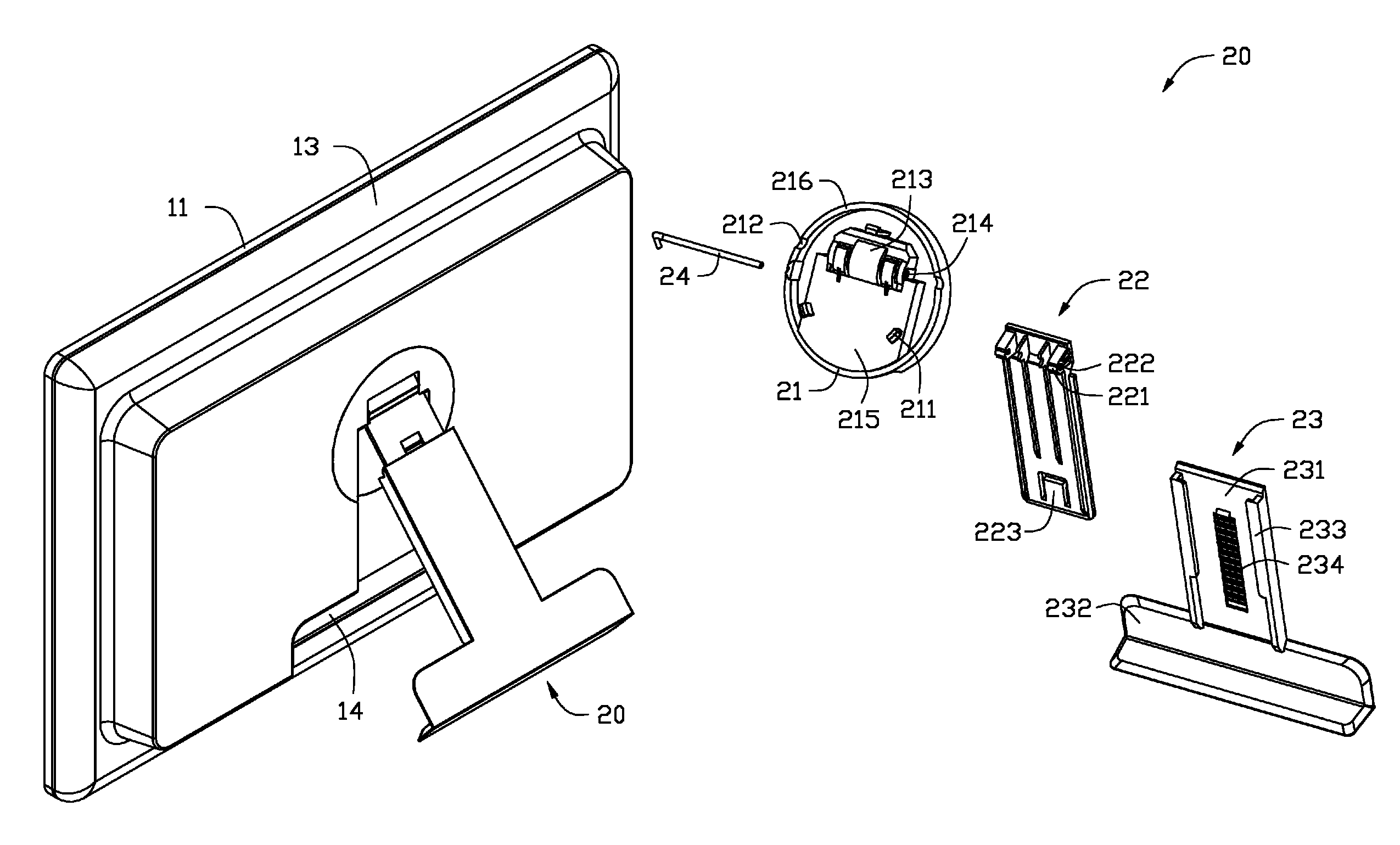
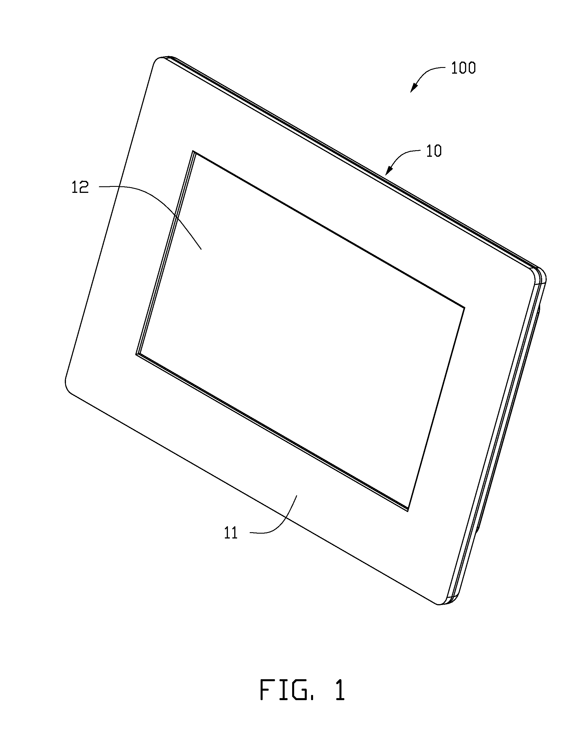
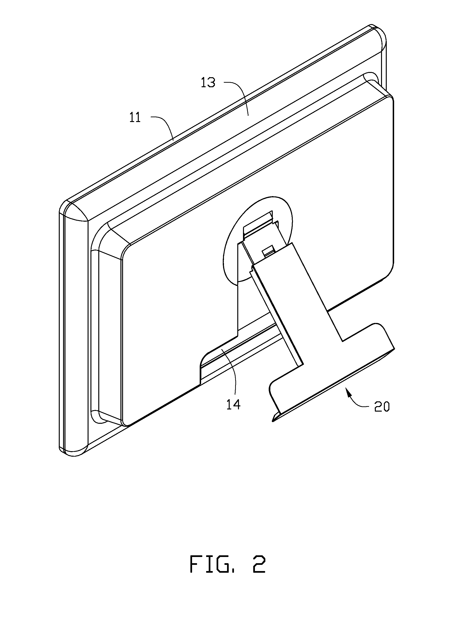
[0013]Referring to FIGS. 1-2, a digital photo frame 100 according to an exemplary embodiment includes a body 10 and a rotary support 20 connected to the back of the body 10. The rotary support 20 is configured to support the main body 10.

[0014]The body 10 includes a front shell 11, a display screen 12 and a back shell 13. The front shell 11 and the back shell 13 cooperatively define a space to receive the display screen 12 and a circuit board (not shown), and the display screen 12 is exposed at the front shell 11. Referring to FIGS. 3 and 4, in the embodiment, a recess 14 is defined in the back shell 13 and a number of connector ports (not shown) are arranged in the recess 14. A round hole 15 is defined approximately in the center of the back shell 13, and is in communication with the recess 14 through a channel 16. The rotary support 20 is received in the space defined corporately by the round hole 15, the channel 16 and the recess 14. In the embodiment, when the rotary support 20 ...


PUM


Abstract

A digital photo frame includes a body, a back shell defining a hole and a rotary support. The rotary support is rotatably connected to the back shell, includes a rotary base rotatably received in the hole, a connection member pivotedly connected to the rotary base, and an elongated support body slidably coupled to the connection member. The connection member includes a spring tab, a support body defining a plurality of channels. The channels are arranged along a lengthwise direction of the connection portion. the spring tab is selectively snappingly engaged in one of the channels. One of the rotary base and the back shell includes a plurality of protrusions, and the other one of the rotary base and the back shell defines a plurality of notches corresponding to the protrusions, the protrusions are snappingly engaging in the respective notches.

Description

BACKGROUND[0001]1. Technical Field[0002]The present disclosure relates to digital photo frame, especially to an digital photo frame with an adjustable support.[0003]2. Description of Related Art[0004]A portable digital photo frames usually includes a support. The support can usually only supports the photo frame in one or two orientations, which can not meet a user's need in specific condition. More over, digital photo frames include many ports, which need one or more covers to cover the ports for preventing dust entering the ports. It is desirable and useful if the support can support the digital photo frame in more orientations and can cover the ports.BRIEF DESCRIPTION OF THE DRAWINGS[0005]Many aspects of the embodiments can be better understood with reference to the following drawings. The components in the drawings are not necessarily drawn to scale, the emphasis instead being placed upon clearly illustrating the principles of the embodiments. Moreover, in the drawings, like ref...

Claims


Application Information

Patent Timeline
Patent Type & Authority Patents(United States)
IPC IPC(8): H05K5/00G06F1/16A47B97/04A47G1/16
CPCF16M11/105F16M11/2021G06F1/1601F16M13/005F16M2200/028F16M2200/044
Inventor PENG, JIU-CHENGCHEN, PING-CHOUTANG, CHILIU, JIAN
Owner HONG FU JIN PRECISION IND (SHENZHEN) CO LTD
Why Eureka
Try Eureka