
Mechanical system for movement along a housing axis

a technology of mechanical system and housing, applied in the field of sensors, can solve the problems of wasting calibration time, insufficient accuracy of gravity measurement, and extremely sensitive gravity sensors, and achieve the effect of minimizing noise and vibration

Active Publication Date: 2013-09-17
SCHLUMBERGER TECH CORP
View PDF12 Cites 0 Cited by
  • Summary
  • Abstract
  • Description
  • Claims
  • Application Information

AI Technical Summary

Benefits of technology

[0006]In view of the above there is a need for an improved mechanism which permits movement of sensors along the length of a tool housing with a minimum of noise and vibrations. The subject technology accomplishes these and other objectives. The subject disclosure provides a drive system without traditional mechanical contacts e.g. metal to metal via gears, therefore, minimizing noise and vibrations in the gravity measurements.

Problems solved by technology

One limitation to using gravity sensors is that the accuracy of the gravity measurement may be insufficient for making gravity density measurements in boreholes.
Gravity sensors are extremely sensitive to vibrations and these vibrations may throw the gravity sensors out of calibration.
Further, even if the sensor remains calibrated after being subjected to vibrations the sensor will take time to settle which is undesirable as it reduces the logging speed and increases the chance of having the tool stuck in the wellbore.

Method used


Image

  • Mechanical system for movement along a housing axis
  • Mechanical system for movement along a housing axis
  • Mechanical system for movement along a housing axis

Examples


Embodiment Construction

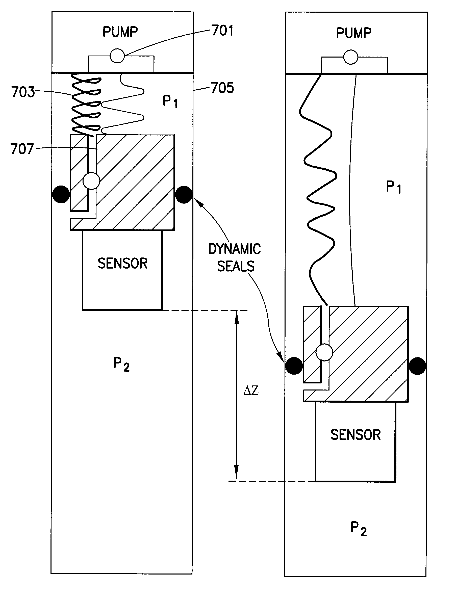
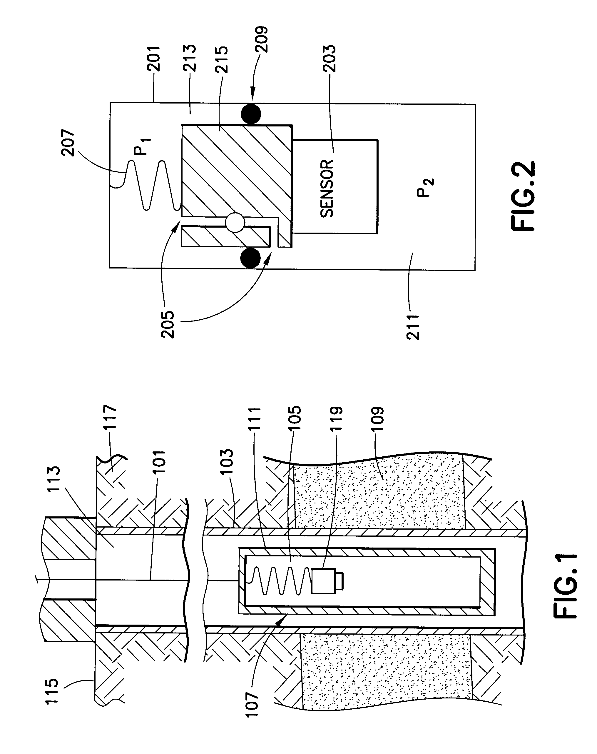
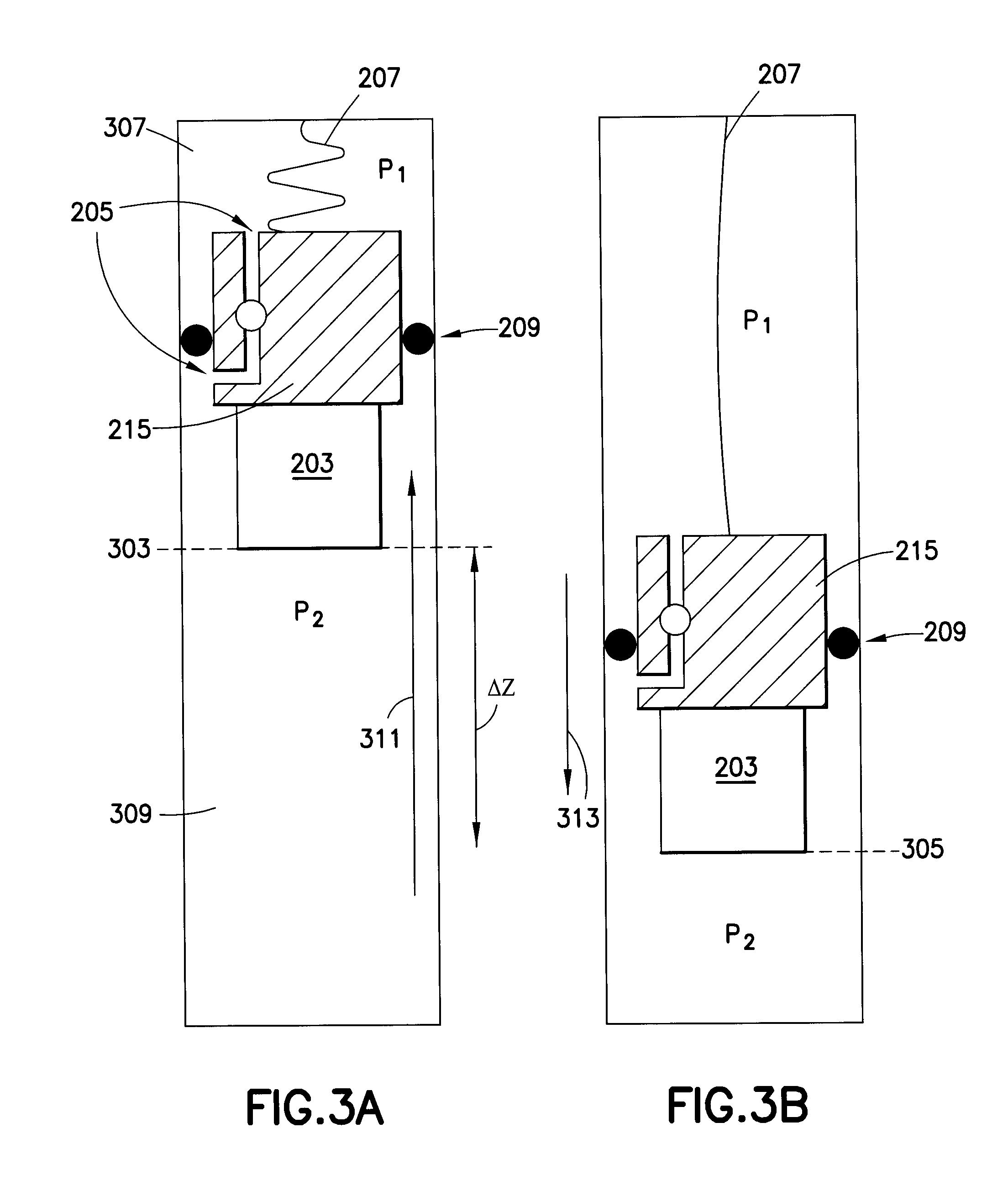
[0018]The present technology is directed to a mechanism for moving objects along the axis of a confining cylinder. More particularly, the present technology is directed to a mechanical system for moving sensors in a longitudinal direction in a housing of an oilfield tool. The direction of motion of the mechanism is in the longitudinal direction of the oilfield tool.

[0019]Embodiments of the present technology comprise a pump. In one non-limiting example, the pump is a bidirectional pump with a first outlet for pumping fluid to operate the system in a first direction and a second outlet for pumping fluid to operate the system in a second direction. These bidirectional pumps are commercially available. In non-limiting examples, these bidirectional pumps may be positive displacement pumps for example, a progressing cavity pump. As will be apparent to one skilled in the art, any commercial available bidirectional pump may be used. Typically, electrical, hydraulic or pneumatic means are u...


PUM


Abstract

A mechanism for moving elements in a fluid filled housing using a pump with the element to be moved attached rigidly to the pump or to a port assembly connected to the pump. The pump assembly or port assembly moves as a result of differential pressure created between a first and a second chamber separated from each other by the pump assembly or port assembly. Movement of the fluid in one direction increases or decreases pressure, the pressure change resulting in a net force in one direction or the other.

Description

FIELD OF THE DISCLOSURE[0001]The subject disclosure generally relates to the field of sensors and more particularly to mechanisms used to move sensors along the length of a housing of an oilfield tool.BACKGROUND OF THE DISCLOSURE[0002]Oil exploration involves evaluating reservoirs to determine the movement or absence of oil, gas, or water as the reservoir fluids are produced. Understanding movement of gas in reservoirs is important to the prevention of premature breakthroughs and optimization of reservoir performance. It is known to use gravity borehole tools to measure characteristics of geologic formation, particularly in the exploitation of hydrocarbon reservoirs found in geologic formations or in the subsurface storage of carbon dioxide or water.[0003]The process of measuring physical properties of earth formations beneath the surface of the earth is commonly referred to as “well logging”. It comprises the step of lowering sensors or testing equipment mounted on robust tool bodi...

Claims


Application Information

Patent Timeline
Patent Type & Authority Patents(United States)
IPC IPC(8): F04B41/06
CPCF04B23/028
Inventor CHEN, KUO-CHIANGJACOBSON, AARONWICKS, NATHANIELOCALAN, MURAT
Owner SCHLUMBERGER TECH CORP
Learn More