Method and apparatus for interconnecting traction cleats and receptacles

a technology of traction cleats and receptacles, which is applied in the field of methods and apparatus for interconnecting traction cleats and cleat receptacles, and can solve the problems of not preventing the cleat from backing itself out, no visible, audible or tactile indication that full insertion had been achieved, and no visible, audible or tactile indication

Active Publication Date: 2013-10-01
PRIDE MFG CO LLC
View PDF26 Cites 6 Cited by
  • Summary
  • Abstract
  • Description
  • Claims
  • Application Information

AI Technical Summary

Benefits of technology

[0019]Therefore, in light of the above, and for other reasons that become apparent when the invention is fully described, it is one object of the present invention to provide improved attachment and locking methods and apparatus between a traction cleat and a shoe-mounted receptacle.
[0024]It is also an object of the invention to provide an attachment arrangement between a cleat and receptacle that is configured to permit minimization of the longitudinal profiles of the cleat and the receptacle, individually and in combination.
[0025]Another object of the invention is to provide locking arrangements between a cleat and receptacle configured to permit minimization of the longitudinal profiles of cleat and the receptacle, individually and in combination.
[0026]It is another object of the present invention to provide attachment and locking apparatus and methods between a traction cleat and a receptacle wherein the receptacle longitudinal dimension can be minimized.
[0028]A further object of the invention is to provide locking apparatus and methods between a cleat and receptacle that provide a cleat installer with positive humanly perceptible feedback upon insertion of the cleat to the desired position in the receptacle.
[0037]The attachment flanges are described as being “thin” in the vertical dimension. By “thin” it is meant that the tapered flange at its thickest portion has a vertical dimension on the order of 1.5 mm or less. The resistance to flexure lost by making the flange that thin is more than compensated for by the additional locking arrangements described herein, and by the small annular spaces between the stem and cleat locking structures that absorb lateral impact instead of the impact being applied directly to the receptacle boss. A primary benefit of the thin flange is the ability to reduce the vertical dimension of the receptacle.

Problems solved by technology

However, in practical use, this friction fit did not prevent the cleat from backing itself out from over time.
In addition, there was no specific stopping point which alerted the installer of the cleat that the stem had been screwed in far enough; that is, there was no “stop” and no visible, audible or tactile indication that full insertion had been achieved.

Method used


Image

  • Method and apparatus for interconnecting traction cleats and receptacles
  • Method and apparatus for interconnecting traction cleats and receptacles
  • Method and apparatus for interconnecting traction cleats and receptacles

Examples


Embodiment Construction

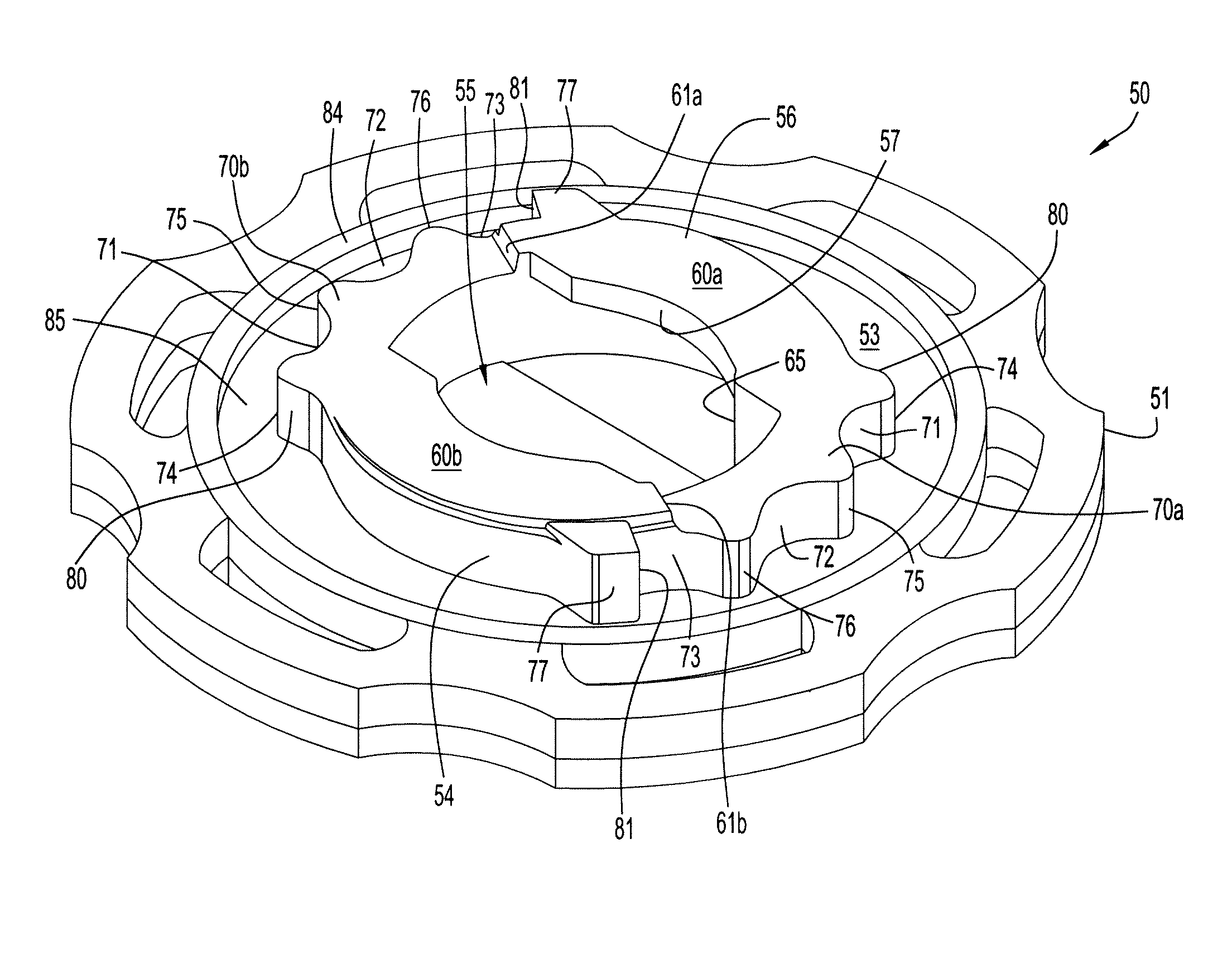
[0073]The specific angular and linear dimensions set forth below are by way of example for particular embodiments to assist in an understanding of the illustrated structure; these dimensions are not to be construed as limiting the scope of the invention.

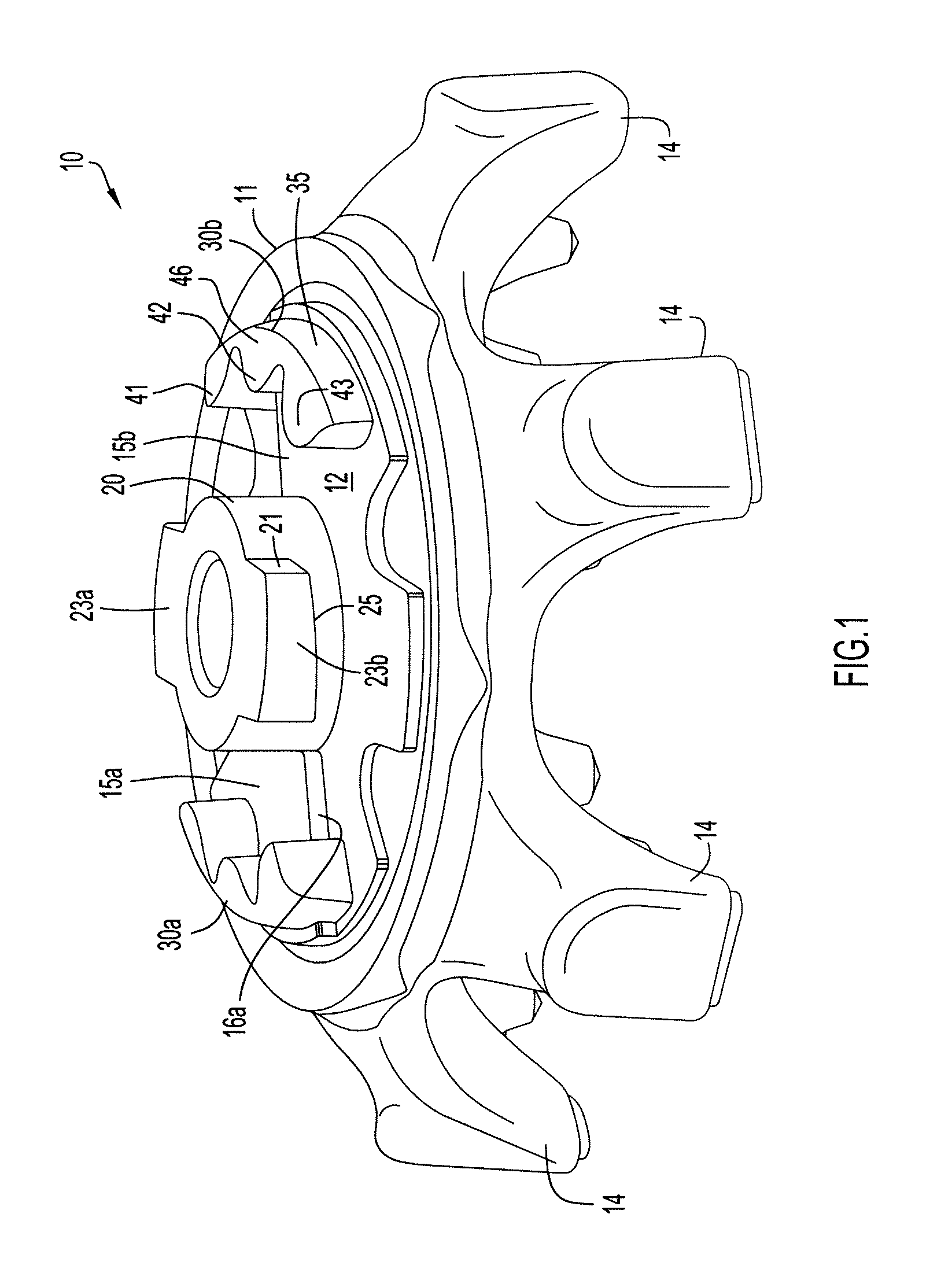
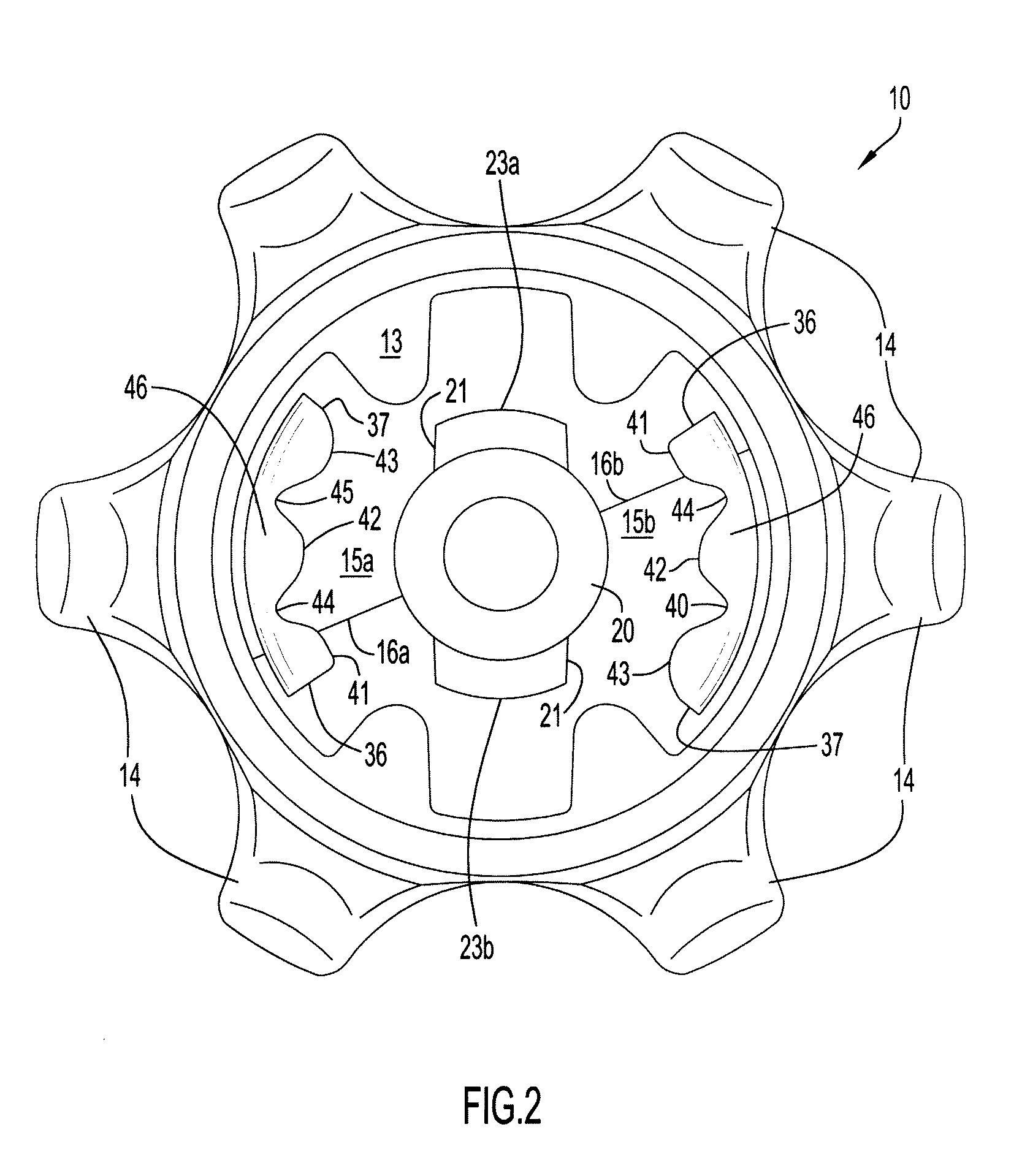
[0074]Referring specifically to FIGS. 1-11 and the embodiments disclosed therein, a traction cleat 10 comprises a hub 11 with a top surface 12 and bottom surface 13. The hub is generally circular but can be otherwise configured, symmetrically or asymmetrically about cleat attachment axis A. Ground engaging traction elements 14 extend generally downward from the hub periphery or bottom surface. It is to be understood that particular traction elements do not form part of the present invention and may be provided as static or dynamic elements in any number, array or orientation. In the particular embodiment illustrated in FIGS. 1-5 there are six traction elements 14 spaced at equal angles in an array that is symmetrical about cleat axis...


PUM


Abstract

A thinner shoe mounted receptacle results from a thin cleat attachment flange received in a shallow receptacle cavity. An angled interface between the cleat and receptacle provide a friction fit engagement to minimize inadvertent disengagement of the cleat and receptacle. Rotational locking occurring inside or outside the cavity further prevents inadvertent cleat rotation. Multiple positionally synchronized angular stops positively define the final angular orientation of the cleat in the receptacle.

Description

CROSS REFERENCE TO RELATED APPLICATION[0001]This application claims priority from U.S. Provisional Patent Application Ser. No. 61 / 168,245 entitled “Low Profile Cleat and Receptacle Assembly and Attachment Method,” filed Apr. 10, 2009. The disclosure in that provisional patent application is incorporated herein by reference in its entirety.BACKGROUND[0002]1. Technical Field[0003]The present invention pertains to an improved method and apparatus for interconnecting traction cleats and cleat receptacles for athletic shoes. Although the preferred embodiments disclosed herein are used primarily in golf shoes, it is to be understood that the interconnection method and structure have application in any shoe that utilizes traction cleats that are selectively attachable to a shoe.[0004]2. Terminology[0005]It is to be understood that, unless otherwise stated or contextually evident, as used herein:[0006]The terms “upper”, “top”, “lower”, “bottom”, “vertical”, “horizontal”, etc., are used for ...

Claims


Application Information

Patent Timeline
Patent Type & Authority Patents(United States)
IPC IPC(8): A43B5/00A43C15/02
CPCA43C15/161A43C15/02
Inventor BURT, JOHN ROBERTSHUTTLEWORTH, LEE PAULKRIKORIAN, RAND J.
Owner PRIDE MFG CO LLC
Why Eureka
Try Eureka