Graphic user interface for a storage system

Active Publication Date: 2006-11-30
IBM CORP
View PDF8 Cites 4 Cited by
  • Summary
  • Abstract
  • Description
  • Claims
  • Application Information

AI Technical Summary

Benefits of technology

[0009] In response to one or more inputs from a user of the storage system, the appearance of the image or images may be further modified, the modification enabling the user to determine characteristics of the storage system in a more efficient and intuitive manner. In addition, the user may interact with the image to make physical alterations to the storage sub-systems.
[0010] In one embodiment of the present invention, a first input from the user generates an enlarged image of one of the elements. The enlarged image provides positive feedback to the user that the element has been selected. A second input enables the user to check and manipulate characteristics of the element.
[0012] In a further alternative embodiment, the user input forms an at least partially transparent overlay on the realistic image of a sub-system. The user may apply further inputs to display characteristics of elements of the sub-system on the overlay, while maintaining the visibility of the underlying images of the elements.

Problems solved by technology

As demands placed upon data storage systems increase and as the volume of data processed by the systems also increases, operation of the storage systems becomes more problematic.

Method used


Image

  • Graphic user interface for a storage system
  • Graphic user interface for a storage system
  • Graphic user interface for a storage system

Examples


Embodiment Construction

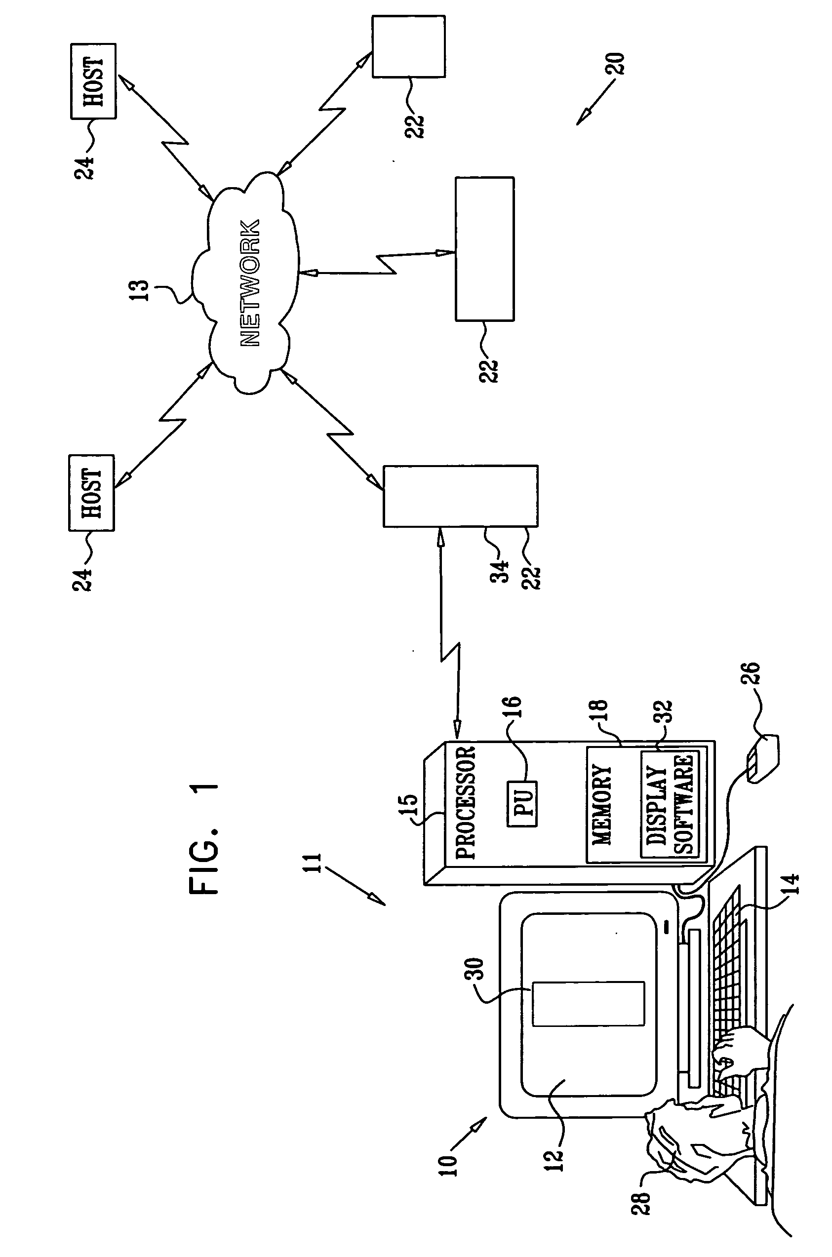
[0055] Reference is now made to FIG. 1, which is a schematic illustration of a graphic user interface (GUI) 10 for a data storage system 20, according to an embodiment of the present invention. System 20 acts as a facility for one or more hosts 24 to read data from, write data to, and store data. System 20 is assumed to comprise one or more physically separate sub-systems 22, and the elements of each sub-system are typically positioned in one respective location and are typically coupled together using cables and / or other physical couplings.

[0056] Storage system 20 is controlled by a system operator 28 via a system control unit 11, typically comprising an off-the-shelf personal computer. Hosts 24, sub-systems 22, and unit 11 may be coupled using any suitable communication method known in the art, including wireless, wired, and / or optical communication methods, and are assumed herein to be coupled by and operate in a network 13.

[0057] Control unit 11 comprises a processing unit 16 ...


PUM


Abstract

A method for interfacing with a storage system. The storage system has a plurality of elements having a visible relationship with each other, and the storage system is coupled to a system control unit including a display. The method includes: drawing an image of the elements on the display, the image showing the visible relationship, and modifying an appearance of one of the elements in the image to represent a property of the element. The method further includes, in response to a first input from a user of the storage system to the system control unit, drawing an enlarged image of the element and representing the property in the enlarged image. The method also includes, in response to a second input from a user of the storage system to the control unit with respect to the enlarged image, representing a further property of the element in the enlarged image.

Description

RELATED APPLICATION [0001] This application is a continuation-in-part to application Ser. No. 11 / 090,444 titled “Graphic User Interface for a Storage System” filed Mar. 24, 2005, which is incorporated herein by reference.FIELD OF THE INVENTION [0002] The present invention relates generally to data storage systems, and specifically to a graphic user interface for facilitating operation of the system. BACKGROUND OF THE INVENTION [0003] As demands placed upon data storage systems increase and as the volume of data processed by the systems also increases, operation of the storage systems becomes more problematic. One of the aspects of operation of storage systems is the interface between an operator of the system and the system itself, and attempts to improve the overall operation by relating to a graphic user interface (GUI) have been made in the prior art. Some of these GUIs use text describing elements of the storage system, and / or icons depicting the elements, to help the operator o...

Claims


Application Information

Patent Timeline
IPC IPC(8): G06T11/20
CPCH04L67/1097H04L41/22
Inventor ZOHAR, OFIRBIRENBOIM, AMIHAYREVAH, YARONHELMAN, HAIMCOHEN, DRORSCHWARTZ, SHEMER
Owner IBM CORP
Why Eureka
Try Eureka