Mounting clip

a technology of mounting clips and clips, which is applied in the direction of hose connections, lighting and heating equipment, and support devices for mini-flashlights, etc., can solve the problems of difficult to remain in place and the cap is not self-supporting, and achieves the effects of easy maintenance, low manufacturing cost, and durable construction

Inactive Publication Date: 2013-10-01
MSB
View PDF18 Cites 30 Cited by
  • Summary
  • Abstract
  • Description
  • Claims
  • Application Information

AI Technical Summary

Benefits of technology

[0007]The clip portion may be oriented in a first direction and the object mounting portion is oriented so that an object having an elongate portion has the elongate portion extending generally orthogonally with respect to the first direction when the object is carried by the object mounting portion. The grasping means may comprise opposing segments of the object mounting portion biased toward each other so as to exert a gripping force on an object carried therebetween. The biasing may result from the clip being formed of a memory retentive material. Optionally, the opposing segments may be dimensioned to form an opening therebetween, wherein at least one of the opposing segments can flex sufficiently away from the other to expand the size of the opening for permitting the object to enter the grasping through the expanded opening.
[0009]A feature of an embodiment of the invention may comprise the mounting portion formed with two barrel grasping portions having different diameters corresponding to two known sizes of flashlights, by way of example. It is an advantage of this invention that the mounting clip will be operable with most current commercially available flashlights. The clip portion and the mounting portion may be formed with spring-biased members that operate to firmly grasp the bill of the cap and the barrel of the flashlight, respectively. As a result, objects, such as flashlights, may will be stably supported on a bill of a cap, a belt worn by a user, and the like, for a hands free operation within a lighted environment. The clip portion may be formed with a different width dimension than the mounting portion. It is anticipated that material forming the clip will be durable in construction, inexpensive of manufacture, carefree of maintenance, facile in assemblage, and simple and effective in use.
[0010]One embodiment if the invention may be constructed with a clip portion and an integral flashlight mounting portion, both of which are made of memory retentive plastic so that the mounting of either portion takes advantage of the spring bias to exert a firm grip on the surface the portion engages. The upper and lower portions of the flashlight mounting portion are formed in a pair of arcuate segments that when taken together form a generally circular barrel grasping portion in two different diameters corresponding to known configurations of mini-flashlights. The surface of the mounting clip can be coated with a rubber-like material that enhances the grip on the surface engaged thereby. The clip portion may be formed with a different width dimension than the flashlight mounting portion.

Problems solved by technology

Generally, these mini-flashlights are not self-supporting.
Thus, it is typically necessary for a user of these mini-flashlights to use one hand to hold and position the light beam emanating from the flashlight, which can be a hindrance if the user is trying to accomplish a task that requires the use of more than one hand.
However, none of the above-identified teachings provide a device that is adapted for use with multiple mini-flashlight sizes and may be positioned on the side of the bill of a cap, by way of example, so that the weight of the device is not pulling down on the cap and making the cap difficult to remain in place.

Method used


Image

  • Mounting clip
  • Mounting clip
  • Mounting clip

Examples


Embodiment Construction

[0024]The present invention will now be described more fully hereinafter with reference to the accompanying drawings, in which embodiments of the invention are shown. This invention may, however, be embodied in many different forms and should not be construed as limited to the embodiments set forth herein. Rather, the embodiments herein presented are provided so that this disclosure will be thorough and complete, and will fully convey the scope of the invention to those skilled in the art.

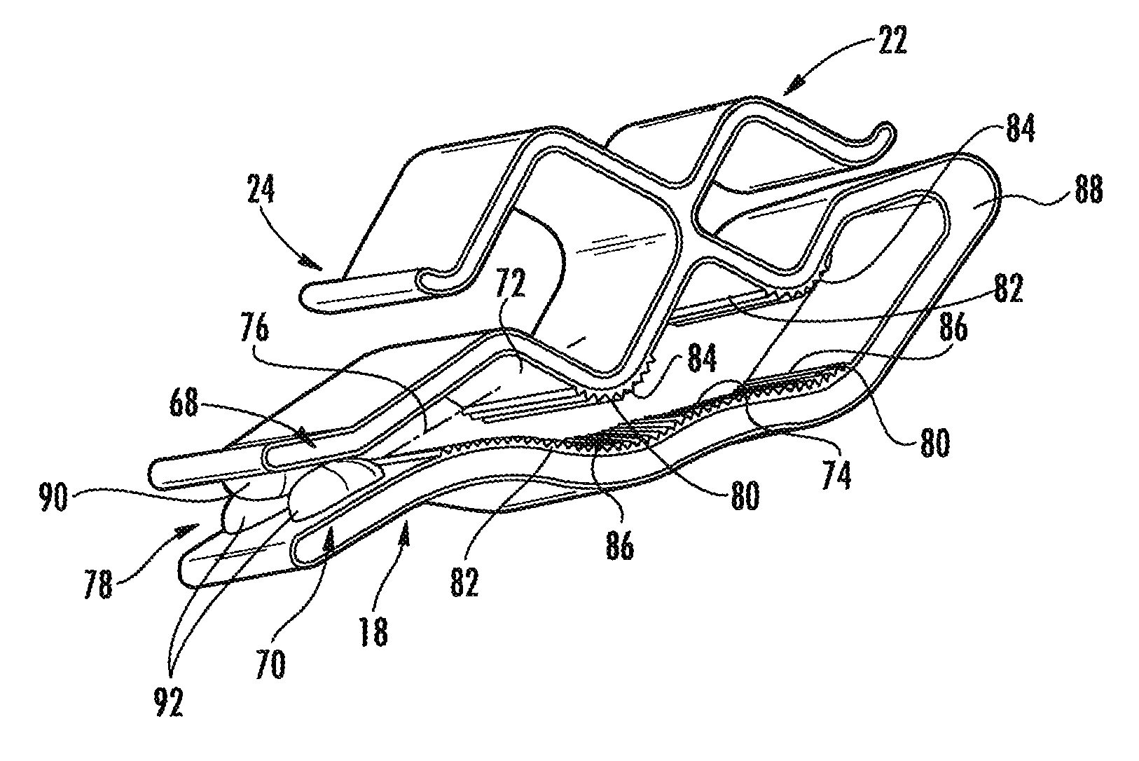
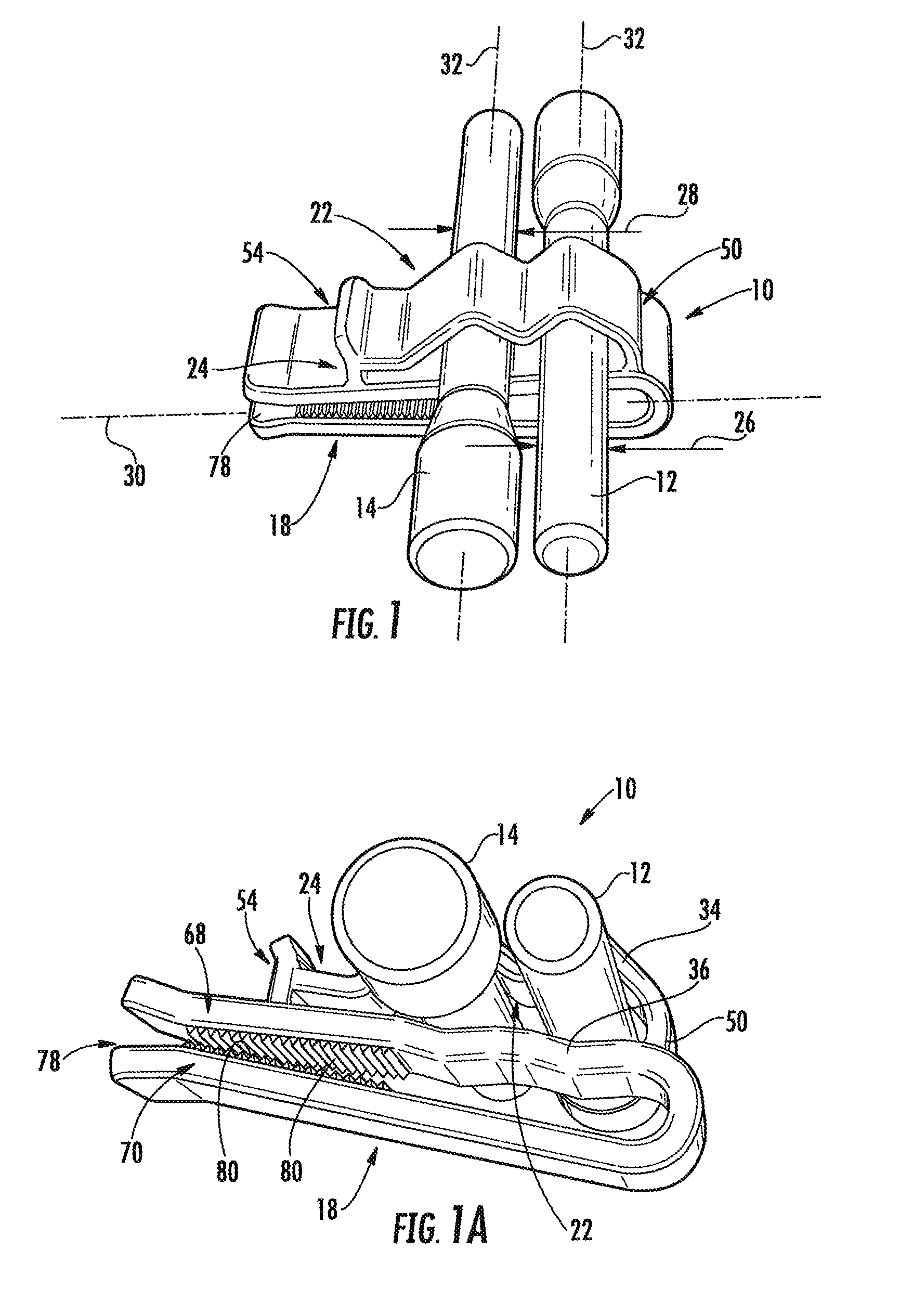
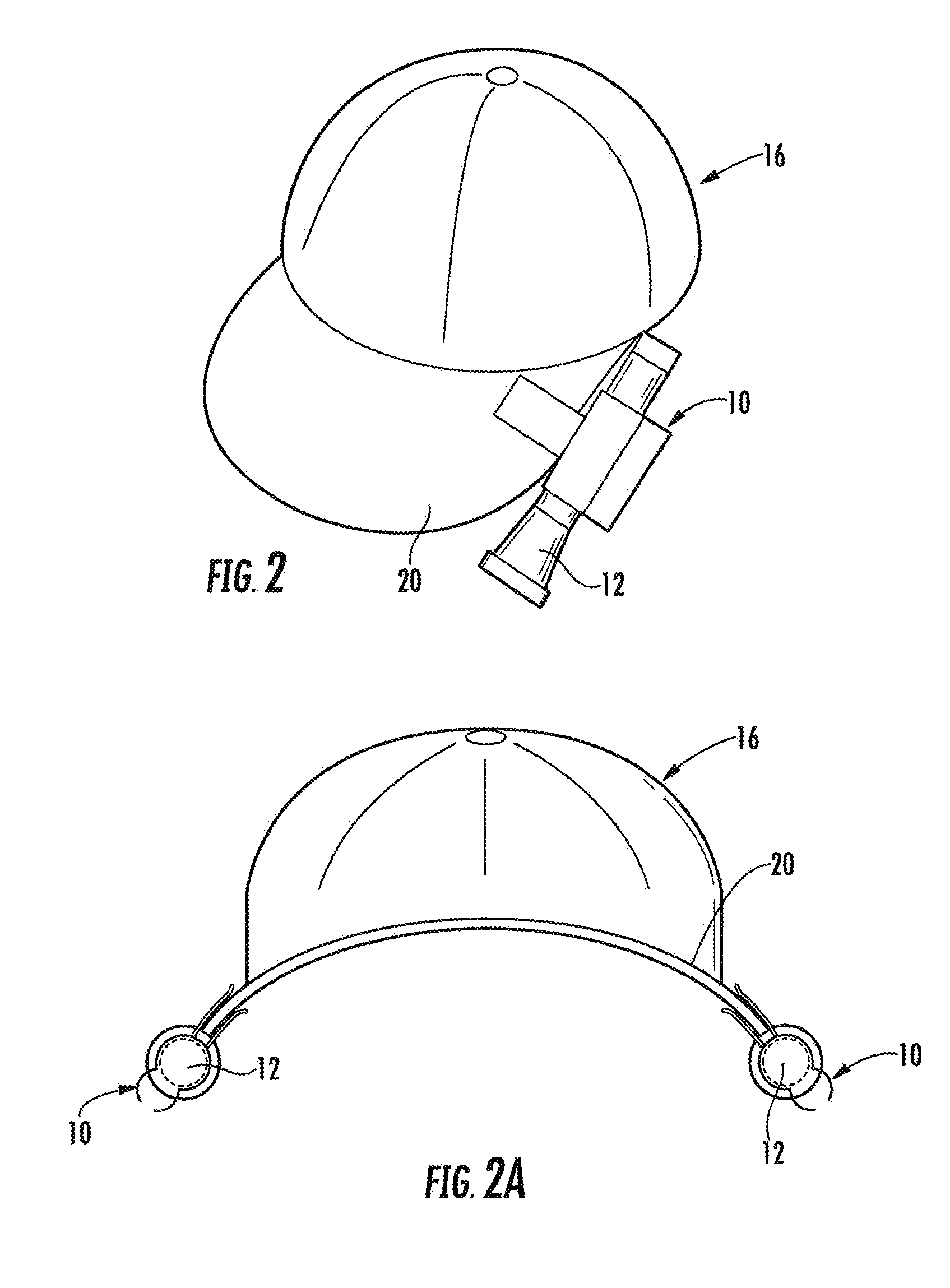
[0025]With reference initially to FIGS. 1, 1A and 2, one embodiment of the invention is herein described as a clip 10 for attaching objects 12, 14 to an article 16. With continued reference to FIGS. 1 and 2, and to FIGS. 3, 3A and 3B, embodiments of the clip 10 comprise a clip portion 18 dimensioned for removably attaching to the article 16, such as a visor or bill 20 of the article 16, herein a cap by way of example. An object mounting portion 22 is formed with the clip portion 18 and grasping mea...


PUM


Abstract

A mounting clip for attaching objects, such as flashlights to an article, such as a hat or belt, includes a clip portion dimensioned for attaching the clip to the article and an object mounting portion formed with the clip portion. Objects of different widths are removably yet snugly grasped within the object mounting portion. The clip portion includes upper and lower members defining a slot for receiving the article through a lip of the slot and frictionally securing the clip to the article.

Description

CROSS-REFERENCE TO RELATED APPLICATIONS[0001]This application is a continuation-in-part of U.S. patent application Ser. No. 11 / 754,443, filed on May 29, 2007, now U.S. Pat. No. 7,703,938 which is a continuation-in-part of U.S. patent application Ser. No. 11 / 311,296, filed on Dec. 19, 2005, entitled “Flashlight Hat Clip”, which claims priority to U.S. Provisional Application No. 60 / 636,905, filed Dec. 18, 2004 the disclosures of which are hereby incorporated by reference herein in their entireties, and all commonly owned.FIELD OF THE INVENTION[0002]This invention relates to an accessory for use in mounting lighting devices to headwear and, more particularly, to a mounting clip that can be detachably mounted on the bill of a cap to mount temporarily a flashlight thereto.BACKGROUND OF THE INVENTION[0003]Flashlights have long been popular as portable light sources and can provide a lightweight, compact package for casting a beam of light. More modern flashlight configurations utilize a ...

Claims


Application Information

Patent Timeline
Patent Type & Authority Patents(United States)
IPC IPC(8): F21V21/088
CPCA42B1/24A42B1/244F21V21/0885Y10T24/344
Inventor BROWN, KENNETH J.
Owner MSB
Why Eureka
Try Eureka