Center pivot wing flotation method and apparatus

a technology of pivot wing and flotation method, which is applied in the direction of agricultural machinery, adjusting devices, agricultural tools and machines, etc., can solve the problems of not providing a completely satisfactory solution, not providing a complete satisfactory solution, etc., to achieve carefree maintenance, low cost, and durable construction

Active Publication Date: 2007-05-01
BLUE LEAF I P INC
View PDF16 Cites 25 Cited by
  • Summary
  • Abstract
  • Description
  • Claims
  • Application Information

AI Technical Summary

Benefits of technology

[0010]It is an even still further object of the instant invention to provide a flotation system for the wings of an agricultural seeder that is durable in construction, inexpensive to manufacture, carefree of maintenance, facile in assemblage, and simple and effective in use.

Problems solved by technology

In some known implements, the pivot connection which is provided between the frame of the wing and the central main frame is arranged so that a rigid connection is formed between the main frame and the wing frames when the wings are lowered to their operative positions, but such a structure has the disadvantage of causing the ground working parts of the implement to vary their relation to the ground surface as the implement passes over uneven terrain.
These designs, too, do not provide a completely satisfactory solution to the problems, i.e., they do not accommodate ground unevenness well, because the wings only pivot about an axis located at their inner ends.
There have been other attempts at improving the flotation of implement wings, some better than others, but improved flotation has generally only resulted from designs that are complex, and expensive, and difficult to operate.

Method used


Image

  • Center pivot wing flotation method and apparatus
  • Center pivot wing flotation method and apparatus
  • Center pivot wing flotation method and apparatus

Examples


Embodiment Construction

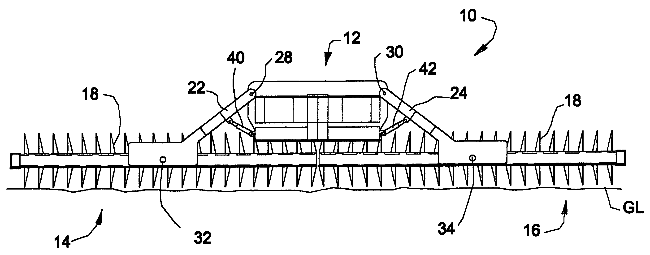
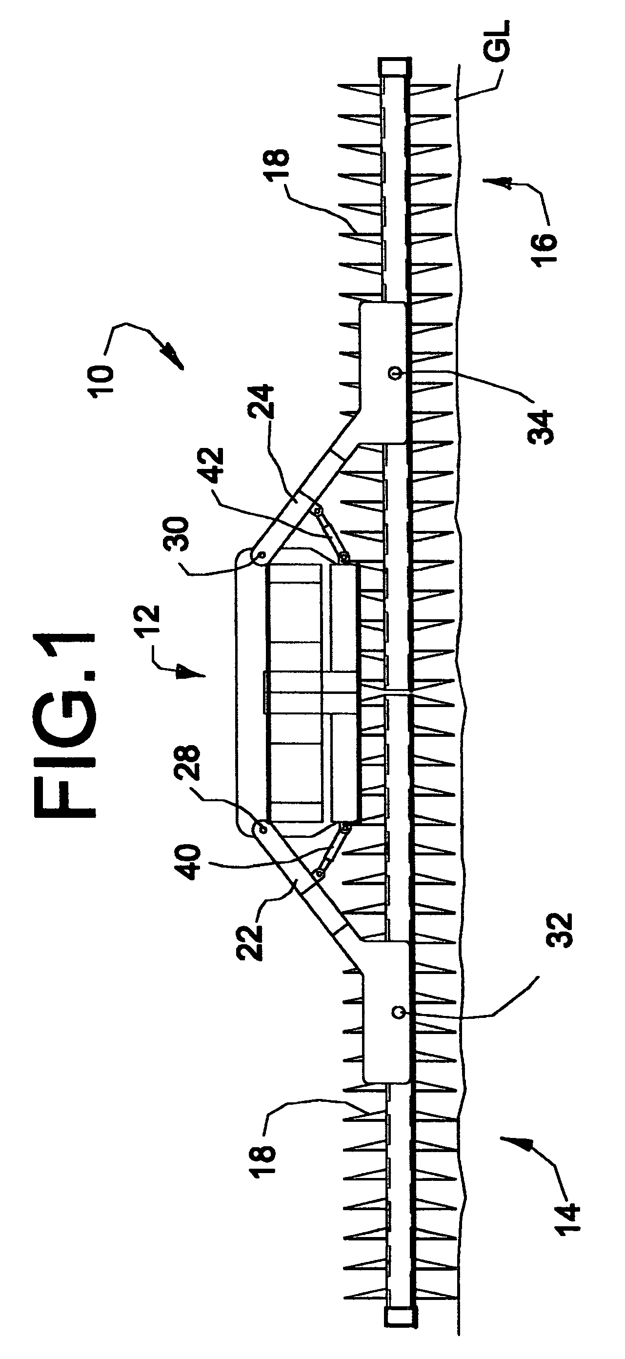
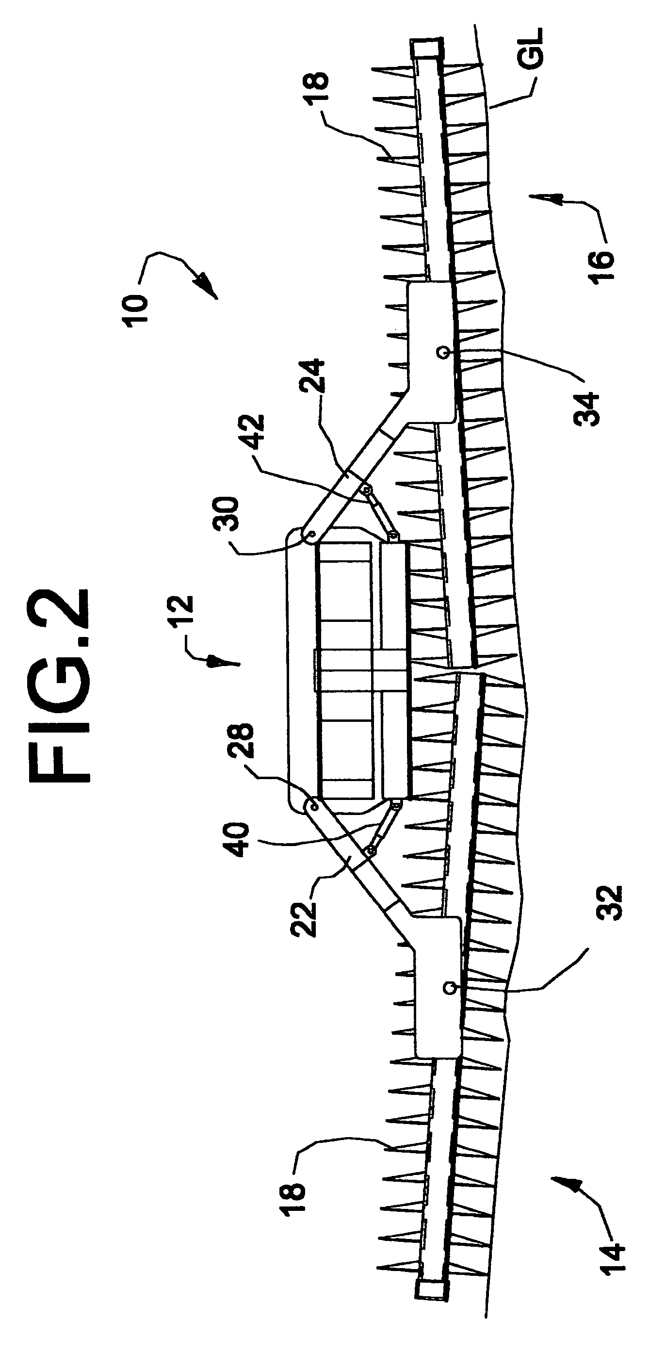
[0015]Many of the fastening, connection, processes and other means and components utilized in this invention are widely known and used in the field of the invention described, and their exact nature or type is not necessary for an understanding and use of the invention by a person skilled in the art, and they will not therefore be discussed in significant detail. Also, any reference herein to the terms “left” and “right”, or “up” and “down” are used as a matter of mere convenience, and are determined by standing at the rear of the mechanism facing in its normal direction of travel. Furthermore, the various components shown or described herein for any specific application of this invention can be varied or altered as anticipated by this invention and the practice of a specific application of any element may already by widely known or used in the art by persons skilled in the art and each will likewise not therefore be discussed in significant detail.

[0016]FIG. 1 depicts a rear elevat...


PUM


Abstract

A method and apparatus for proving a flotation for the wings of a foldable wing of an agricultural seeder that are centrally suspended from the main frame such that individual wings are pivotable centrally of the longitudinal axis therefore to better follow the contours of the ground.

Description

BACKGROUND OF THE INVENTION[0001]The present invention relates generally to a method and apparatus for providing flotation to a wing of a multi-piece toolbar of an agricultural implement, and more particularly to such method and apparatus that employs a center pivot arrangement on the wing of an agricultural seeder.[0002]It is well known that various agricultural implements, such as tillage equipment, seeders, and crop harvesting equipment are constructed in large part of multiple sections arranged end to end transversely to the direction of travel of the implement to provide a relatively wide operational path. Of course, in general, the wider the operational path, the more efficient and cost effective the process, and in farming as in any other business, time is money.[0003]Most often the implement includes a main structural frame centrally mounted on its own wheel structure, and the other sections, which include toolbars and structural members, that are usually disposed at both en...

Claims


Application Information

Patent Timeline
Patent Type & Authority Patents(United States)
IPC IPC(8): A01B49/00A01B63/10A01B73/04A01C5/00A01C7/08A01C7/20
CPCA01B73/044A01C7/20A01C7/208
Inventor GUST, JACOB N.WAKE, WILLIAM A.
Owner BLUE LEAF I P INC
Why Eureka
Try Eureka