Extraction device, particularly for mining, and method for controlling the extraction device

a technology of extraction device and extraction device, which is applied in the direction of cutting machine, earthwork drilling and mining, propulsion, etc., can solve the problems of short service life of magnetic measuring system, large amount of wear, and inability to develop the technical implementation of system, etc., to achieve high system reliability, reliable detection of drive chain condition, and long service life

Active Publication Date: 2013-10-08
CATERPILLER GLOBAL MINING EURO GMBH
View PDF9 Cites 31 Cited by
  • Summary
  • Abstract
  • Description
  • Claims
  • Application Information

AI Technical Summary

Benefits of technology

[0005]The invention of this application relates to an extraction device and a method for controlling an extraction device which make it possible to reliably detect the chain condition of the drive chain using a contactless sensor unit and which have a markedly longer service life with a high level of system reliability.
[0007]The detector, which is constructed as a detector field, and the transmitter for the magnetic field may be arranged next to one another on the same side. In a preferred embodiment, the detector and transmitter are arranged opposite one another such that the transmitter introduces the magnetic field into the chain links or entrainers on the one side, and the magnetic field detectors of the detector field scan the magnetic field that is transmitted by the chain links or entrainers on the other side of the passage. To enable hanging chains in particular to be reliably detected, it is particularly advantageous if the detector field extends over the height of the passage, with a plurality of detectors. In one preferred embodiment, the detector field includes a plurality of magnetic field detectors that are arranged next to one another and a plurality of magnetic field detectors that are arranged above one another, in order to detect over a sufficiently large range the alternating magnetic field that is transmitted or passed on by the chain link or entrainer that is to be detected in a direction transverse to movement of the drive chain. To simplify the calculation work, in this arrangement the magnetic field detectors may be arranged in rows and columns at a constant spacing. Because the magnetic field detectors are arranged in two dimensions in the detector field, the magnetic field that is transmitted can be measured and scanned using magnetic field detectors that where appropriate measure and detect only the horizontal portions of the transmitted magnetic field.

Problems solved by technology

Since the magnetic transducer is arranged, with the measuring device, in the floor panel of the outgoing run, a large amount of wear is produced which only allows a short service life for a magnetic measuring system of this kind.
It has not therefore been possible to develop the technical implementation of the system for detecting hanging chain and other chain conditions which is known from DE 34 06 519 A1 for mass production.

Method used


Image

  • Extraction device, particularly for mining, and method for controlling the extraction device
  • Extraction device, particularly for mining, and method for controlling the extraction device
  • Extraction device, particularly for mining, and method for controlling the extraction device

Examples


Embodiment Construction

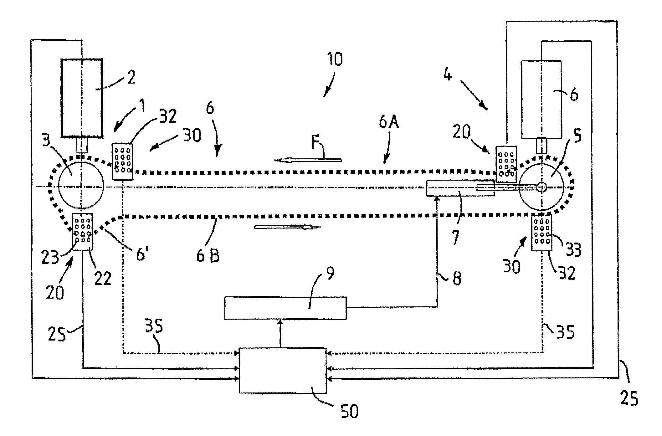
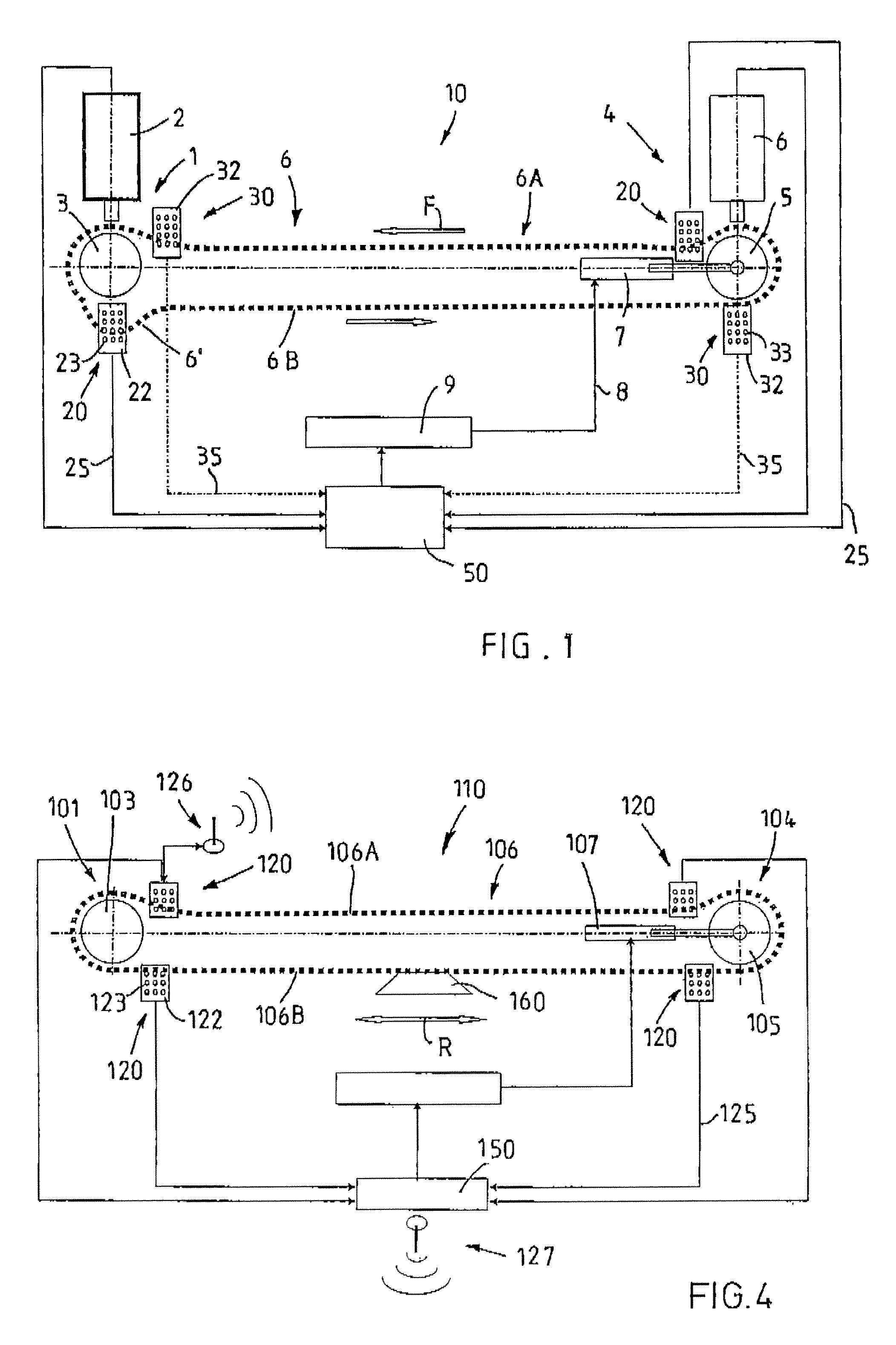
[0025]Referring now to the drawings wherein the showings are for the purpose of illustrating preferred and alternative embodiments of the invention only and not for the purpose of limiting same, FIG. 1 shows, in a schematic illustration of the system, a conveyor device which is designated overall by reference numeral 10, for subterranean mining. The conveyor device 10 includes, in a manner known per se, a first drive station 1 having a schematically illustrated drive motor 2 and a sprocket 3 and, at the other end of the conveyor device 10, a second drive station 4 once again having a sprocket 5 and an associated drive motor 6. The drive motors 2 and 6 may in principle take any form suitable for the intended purpose and be constructed as synchronous motors, frequency converter motors or similar, and include gears, regulating means, overload clutches and similar. Between the two sprockets 3, 5 there circulates, in the direction of conveying indicated by the arrow F, an endless scraper...


PUM


Abstract

An extraction device, particularly for mining, having two drive stations and a drive chain which extends between the sprockets thereof. So that hanging chain or chain wear to a conveyor chain, in the case of a conveyor device, or to a plow chain, in the case of a plow device, can be detected, magnetic sensor units for detecting at least one chain condition of the drive chain are provided, wherein each sensor unit includes a transmitter, which is formed by a static or dynamic magnetic field generator, and a detector field, which is provided with a plurality of magnetic field detectors, as a detector, the detector and the transmitter being arranged to the side of a passage for the run of the drive chain that is to be scanned. The invention also relates to a method for controlling an extraction device for preventing hanging chain.

Description

[0001]This application claims priority to and the benefit of the filing date of International Application No. PCT / EP2008 / 007327, filed Sep. 8, 2008, which application claims priority to and the benefit of the filing date of German Application No. 10 2007 043 043.6, filed Sep. 11, 2007, both of which are hereby incorporated by reference into the specification of this application.[0002]The invention relates to an extraction device, particularly for mining, having a first drive station and a second drive station which is preferably capable of being tensioned by a tensioning means, having sprockets which are mounted in the drive stations, having a drive chain which includes chain links, may be moved and / or deflected by means of the motor-drivable sprockets and extends between the sprockets in the form of an upper run and a lower run, and at least one sensor unit for detecting at least one chain condition of the drive chain in the upper run or the lower run. The invention also relates to...

Claims


Application Information

Patent Timeline
Patent Type & Authority Patents(United States)
IPC IPC(8): B65G23/44
CPCB65G23/44E21C29/14E21F13/066
Inventor MERTEN, GERHARDSCHURER, KARL-HEINZWIRTZ, JORGBAUMLER, MANFREDBOKER, UWE
Owner CATERPILLER GLOBAL MINING EURO GMBH
Why Eureka
Try Eureka