Check patentability & draft patents in minutes with Patsnap Eureka AI!

Exhaust gas purification apparatus

a technology of exhaust gas and purification apparatus, which is applied in mechanical apparatus, machines/engines, separation processes, etc., can solve the problems of insignificant effect, difficulty in controlling hc adsorption capacity, and increase the amount of hcs flowing out into the atmosphere, so as to achieve sufficient level of light-off hc activity, improve hc purification efficiency, and restore nox storage capacity

Active Publication Date: 2013-10-22
ISUZU MOTORS LTD
View PDF20 Cites 5 Cited by
  • Summary
  • Abstract
  • Description
  • Claims
  • Application Information

AI Technical Summary

Benefits of technology

This configuration effectively prevents HC emissions during acceleration by maintaining the HC adsorption material in a low-temperature region, allowing for efficient HC adsorption until the catalyst reaches its activation temperature, thus improving NOx reduction efficiency and reducing the need for costly control measures like fuel reduction or stopping rich air-fuel ratios.

Problems solved by technology

Accordingly, if the optimal control for the amount of NOx released from the NOx storage reduction catalyst is not performed, there arises a concern that the amount of HCs flowing out into the atmosphere may increase.
Accordingly, when the temperature of the exhaust gas rapidly rises at such time as acceleration, there arises a problem that the effect is insignificant against the prevention of the HC outflow.
However, in the former, depending on the running speed, the temperature of the HC adsorbing agent catalyst deposited in the underfloor part varies; therefore, there arises a problem of difficulty in controlling the HC adsorption capacity.
In the latter, since no NOx catalyst of the selective reduction type is provided on the downstream side, there is a problem that HCs desorbed from the HC adsorption material flows out.
Accordingly, there is a problem that not only the system for exhaust gas purification becomes long but also installation of the system takes time as it has two parts of the device.

Method used


Image

  • Exhaust gas purification apparatus
  • Exhaust gas purification apparatus
  • Exhaust gas purification apparatus

Examples


Embodiment Construction

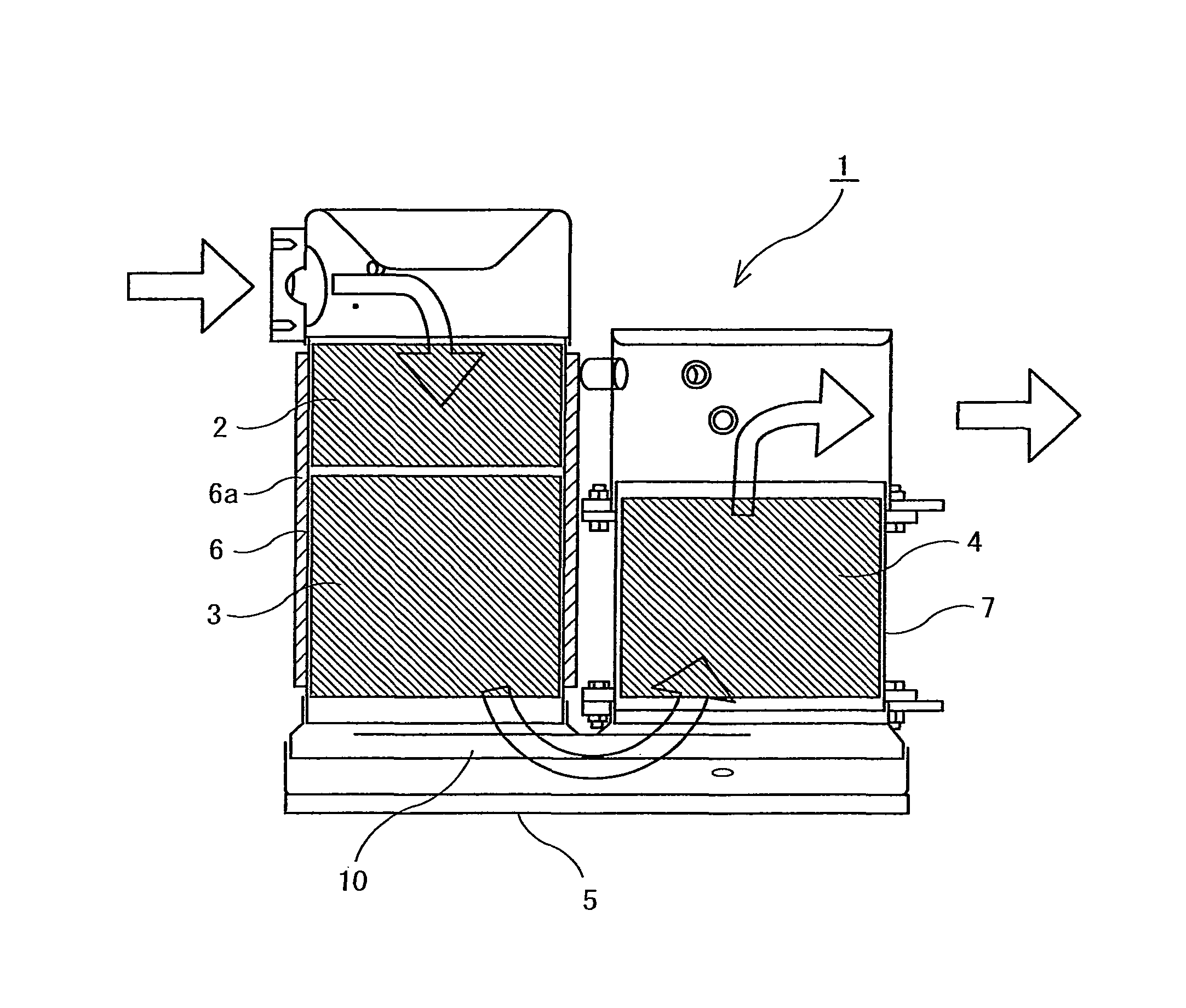
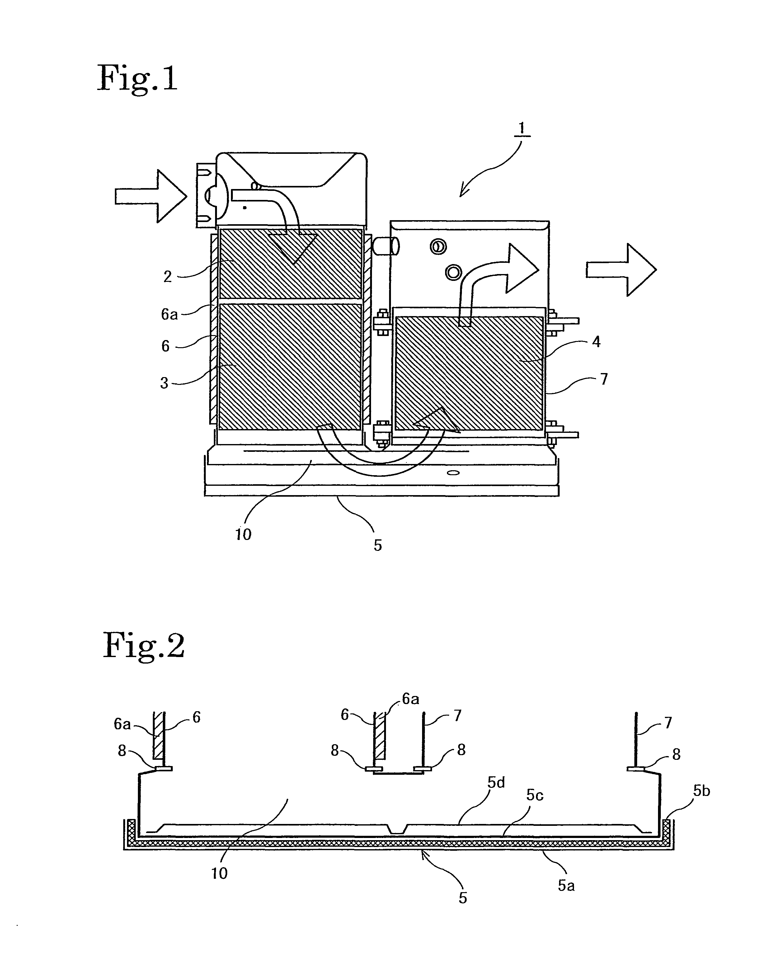
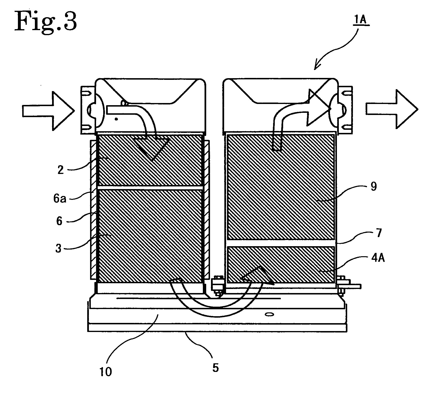
[0028]Hereinafter, an exhaust gas purification apparatus of embodiments according to the present invention will be described by referring to the drawings. FIG. 1 shows the constitution of an exhaust gas purification apparatus 1 of a first embodiment of the present invention. The exhaust gas purification apparatus 1 is an apparatus to be disposed in an exhaust passage of an engine (internal combustion engine). The apparatus 1 is formed by including from the upstream side thereof an oxidation catalyst 2, a three-way catalyst or a NOx storage reduction catalyst 3 which serves as a first exhaust gas treatment member, and a HC adsorption material 4 which serves as a second exhaust gas treatment member having a HC adsorbing function. Hereinafter, the case where a NOx storage reduction catalyst is used as the first exhaust gas treatment member is taken as an example for the description; however, the present invention is also applicable to the case of employing a three-way catalyst.

[0029]Th...


PUM

PropertyMeasurementUnit
temperatureaaaaaaaaaa

Abstract

An exhaust gas purification apparatus including a first exhaust gas treatment member carrying an oxidation catalyst, a three-way catalyst, or a NOx storage reduction catalyst which is used for purifying exhaust gas from an internal combustion engine, a second exhaust gas treatment member having a hydrocarbon (“HC”) storing function disposed on the downstream side of the first exhaust gas treatment member, and a heat dissipating unit disposed between the first exhaust gas treatment member and the second exhaust gas treatment member. An upstream side of the heat dissipating unit is formed into a heat insulating structure, and a further upstream side thereof is formed into a heat retaining structure. Even when an internal combustion engine is accelerating, the exhaust gas flowing into the HC adsorption material can be cooled efficiently and HC can be adsorbed before the temperature of the three-way catalyst or the NOx purification catalyst rises to an HC light-off temperature.

Description

CROSS-REFERENCE RELATED APPLICATION[0001]This application claims the benefit under U.S.C. Section 371, of PCT International Application No. PCT / JP2009 / 060344, filed Jun. 5, 2009 and Japanese Application No. 2008-166324 filed Jun. 25, 2008, the contents of which are incorporated herein by reference.TECHNICAL FIELD[0002]The present invention relates to an exhaust gas purification apparatus including a catalyzer, such as a three-way catalyst and a NOx purification catalyst, the exhaust gas purification apparatus using a hydrocarbon (“HC”) adsorption material, such as zeolite, and being capable of largely reducing an amount of HCs flowing out into the atmosphere by an arrangement of the catalyzer, the HC adsorption material, and a heat dissipating unit.BACKGROUND ART[0003]In regard to countermeasures taken against the outflow of HCs in a system for exhaust gas purification disposed in an internal combustion engine mounted in an automobile, a material having a microporous structure, such...

Claims


Application Information

Patent Timeline
Patent Type & Authority Patents(United States)
IPC IPC(8): F01N3/02
CPCF01N3/02F01N3/0814F01N3/0835F01N3/0842F01N13/14F01N3/106F01N3/28F01N13/0097B01D53/9422B01D53/944B01D53/9445B01D2255/912F01N2240/10Y02T10/22Y02T10/12
Inventor NAGAOKA, DAIJINAKADA, TERUOOOGUSHI, AKIHIDEYUZA, HIROYUKI
Owner ISUZU MOTORS LTD
Features
  • R&D
  • Intellectual Property
  • Life Sciences
  • Materials
  • Tech Scout
  • Unparalleled Data Quality
  • Higher Quality Content
  • 60% Fewer Hallucinations
Learn More