
Retracting storage tray system with locking trunnion

a technology of locking trunnion and storage tray, which is applied in the field of storage units, can solve the problems of difficult use, flimsy cup holders which lack structural integrity, and limited placement of conventional cup holders

Inactive Publication Date: 2013-11-05
FORD GLOBAL TECH LLC
View PDF34 Cites 5 Cited by
  • Summary
  • Abstract
  • Description
  • Claims
  • Application Information

AI Technical Summary

Benefits of technology

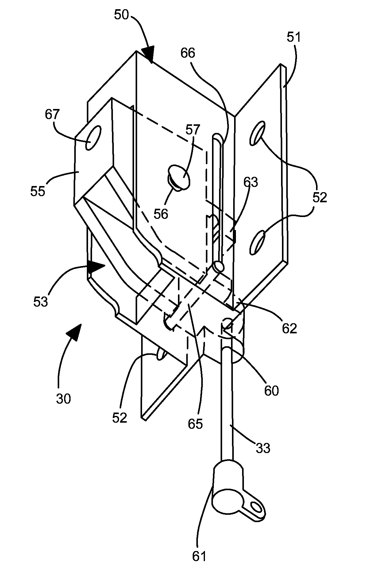
[0006]In one aspect of the invention, a retractable tray system deployable from a vertical panel, includes a housing with a recess configured to lie behind the vertical panel. A trunnion carriage is mounted to the recess with a pair of pivot holes along a pivot axis. A trunnion body is rotatably mounted to the carriage for rotating about the pivot axis between a retracted position and a deployed position. A push member is slidable within the trunnion carriage between a first end of travel and a second end of travel. Moving the push member from the first end of travel to the second end of travel transfers a force against the trunnion body to move it from the retracted position to the deployed position. When the push member is at the second end of travel then the push member locks the trunnion body against movement from the deployed position toward the retracted position. Moving the push member from the second end of travel to the first end of travel transfers a force against the trunnion body to move it from the deployed position to the retracted position. A tray is coupled to and movable with the trunnion body, wherein the tray retracts vertically in the recess when the trunnion body is in the retracted position, and wherein the tray deploys horizontally outward from the recess when the trunnion body is in the deployed position.

Problems solved by technology

Readily accessible and plentiful cup holders are desired by users of vehicles and other seating environments such as theaters and stadiums In some locations such as the rear seats of a vehicle passenger compartment, the locations for placing a conventional cup holder have been very limited due to the absence of horizontal surfaces and the lack of depth behind the available vertical surfaces (such as the trim surface of a side door or the back surface of the front passenger seats or console).
Many prior attempts to package cup holders in these locations have produced flimsy cup holders which lack structural integrity, are difficult to use, and require excessive space within the wall panel from which it deploys.

Method used


Image

  • Retracting storage tray system with locking trunnion
  • Retracting storage tray system with locking trunnion
  • Retracting storage tray system with locking trunnion

Examples


Embodiment Construction

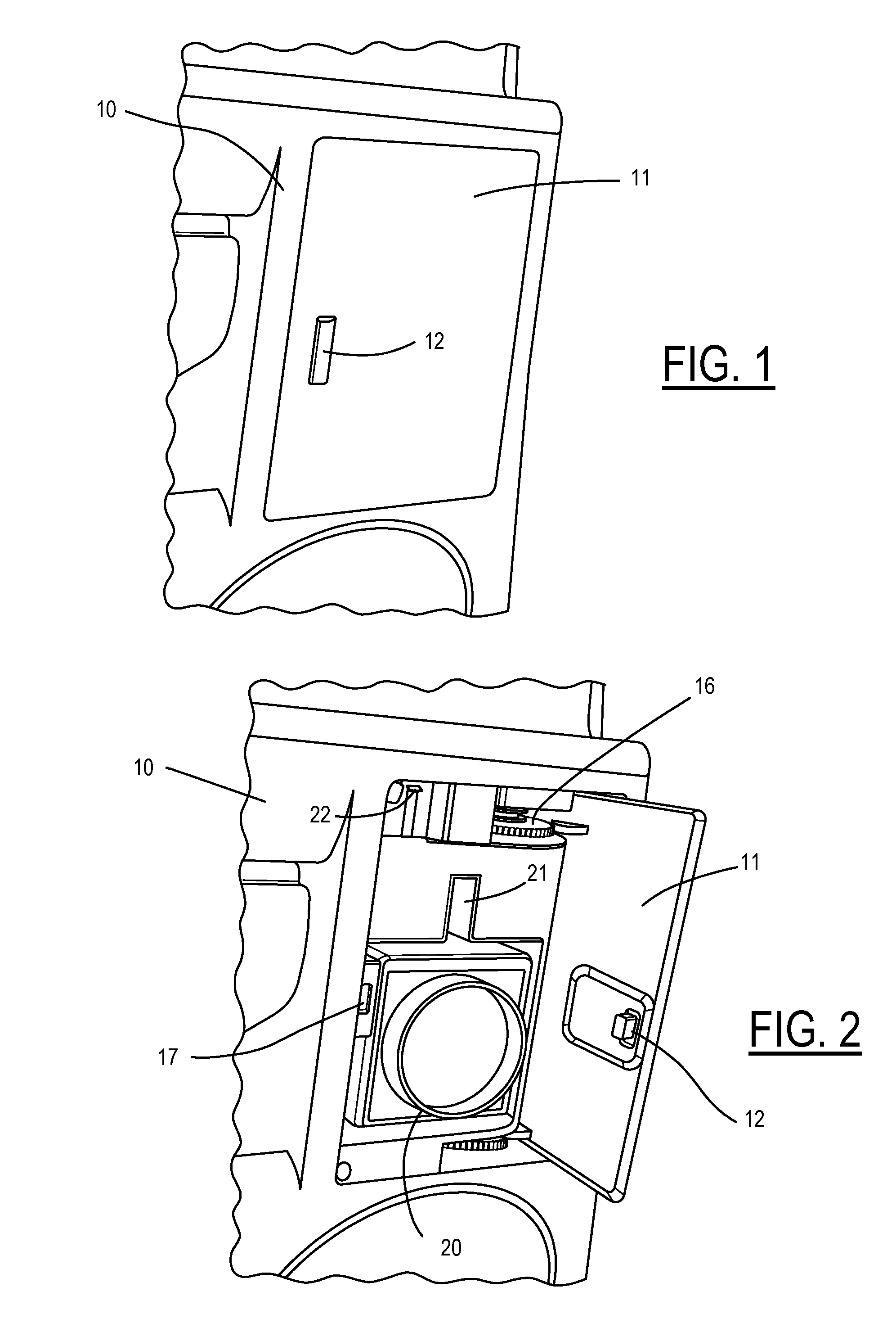
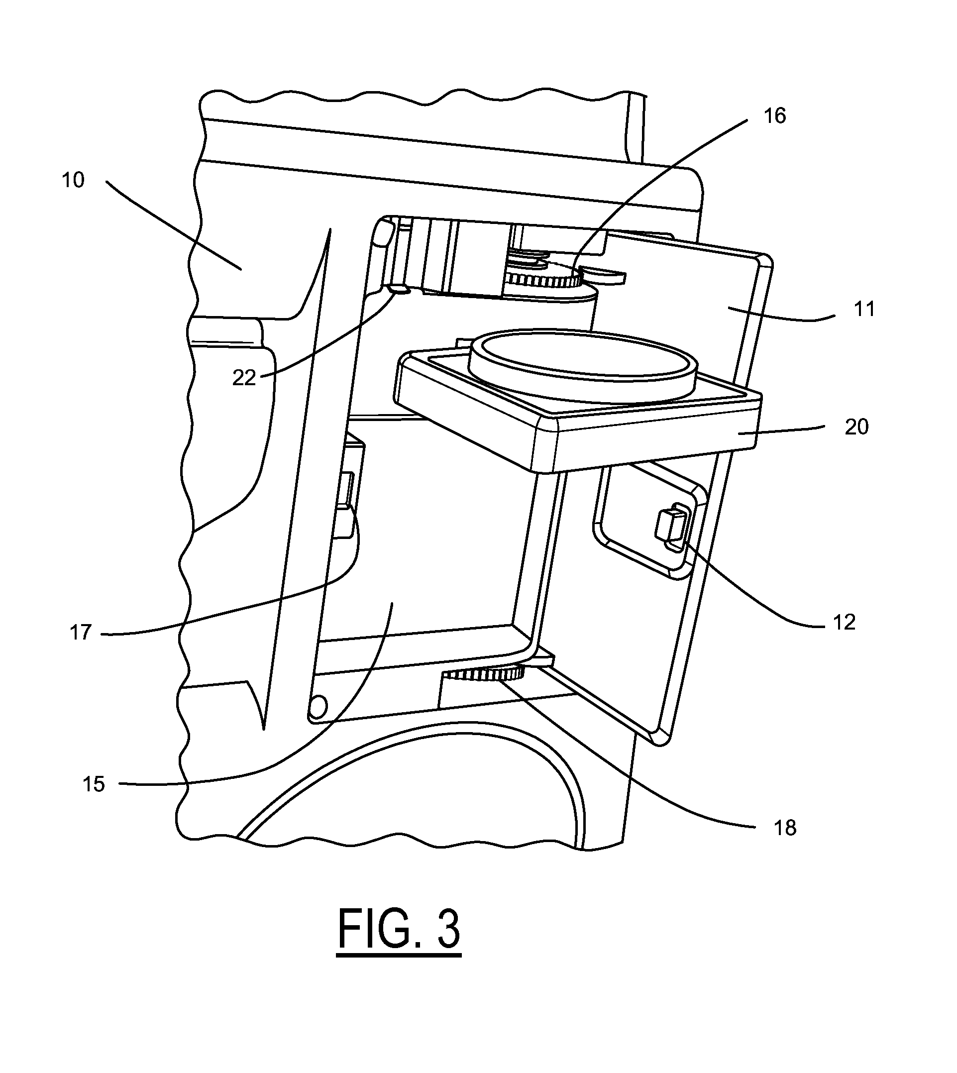
[0018]Referring now to FIG. 1, a deployable tray system is mounted to a vertical panel 10 such as a vehicular door trim panel, a seat back (such as for a vehicle seat or a theatre seat), or a wall of a room. A swinging door 11 opens in response to pressing a latch tab 12 to reveal a deployable tray system as shown in FIG. 2. A recessed housing 15 supports a hinges 16 and 18 for door 11. Housing 15 may be an integral part of vertical panel 10 or may be mounted as a separate component. Latch tab 12 interfaces with a catch 17 on the edge of housing 15. A tray 20 has a retracted position shown in FIG. 2 wherein the retracted tray lies vertically within recessed housing 15. Housing 15 includes a slot 21 through which tray 20 is coupled with a trunnion mechanism (described more fully below) for pivoting tray 20 upward to a deployed position shown in FIG. 3. A push tab 22 is linked to the trunnion mechanism so that pressing down on push tab 22 from the position shown in FIG. 2 to the posit...


PUM


Abstract

A tray system has a trunnion carriage mounted to a recess in a housing. A trunnion body is rotatably mounted to the carriage. A push member is slidable within the carriage. Moving the push member from a first end of travel to a second end of travel transfers a force against the trunnion body to move it to a deployed position. When the push member is at the second end then it locks the trunnion body against movement out from the deployed position. Moving the push member back to the first end transfers a force against the trunnion body to move it to the retracted position. A tray coupled to and movable with the trunnion body retracts vertically in the recess when the trunnion body is in the retracted position and deploys horizontally outward from the recess when the trunnion body is in the deployed position.

Description

CROSS REFERENCE TO RELATED APPLICATIONS[0001]Not Applicable.STATEMENT REGARDING FEDERALLY SPONSORED RESEARCH[0002]Not Applicable.BACKGROUND OF THE INVENTION[0003]The present invention relates in general to storage units such as cup holders in vehicles, and, more specifically, to a mechanism for deploying a stowable tray from a vertical panel.[0004]Readily accessible and plentiful cup holders are desired by users of vehicles and other seating environments such as theaters and stadiums In some locations such as the rear seats of a vehicle passenger compartment, the locations for placing a conventional cup holder have been very limited due to the absence of horizontal surfaces and the lack of depth behind the available vertical surfaces (such as the trim surface of a side door or the back surface of the front passenger seats or console). Due to the limited area and the potential interference of a cup holder with a passenger's movements into or out of their seat (especially for a rear s...

Claims


Application Information

Patent Timeline
Patent Type & Authority Patents(United States)
IPC IPC(8): B60N3/10B60R7/04
CPCB60N3/10
Inventor MIKLAS, JOHN L.
Owner FORD GLOBAL TECH LLC
Learn More