Candle assembly and fuel element therefor

a fuel element and assembly technology, applied in the field of casing assemblies, can solve the problems of affecting the use of casings,

Active Publication Date: 2013-11-05
SC JOHNSON & SON INC
View PDF269 Cites 6 Cited by
  • Summary
  • Abstract
  • Description
  • Claims
  • Application Information

AI Technical Summary

Benefits of technology

[0013]In another embodiment of the invention, a method of providing a candle assembly comprises the steps of providing a support structure having a surface surrounding a depression in a central portion thereof, providing a fuel element comprised of a fuel having a volatile material therein, wherein the fuel element includes a wick retainer and a wick disposed therein, and creating a capillary path through the wick retainer such that the capillary path supplies fuel to the wick when a flame is present on the wick, thereby allowing substantially all of the fuel to be depleted.

Problems solved by technology

One safety concern of some candles and candle assemblies is flashover, whereby the wax reaches an unsafe temperature and causes combustion.
One disadvantage of previous candle assemblies is that such assemblies typically leave an amount of unused wax on the support structure because of the aforementioned methods to prevent flashover.
Even in assemblies that do not try to prevent flashover, fuel may be left over, which leaves a negative impression on the consumer.
Leftover and excess wax is an even larger problem when the support structure for the candle is reused with another single-use wax element.
Leftover wax may cause unpleasant mixing when the new wax element is added to the support structure and an associated wick is lit, thereby sending fragrance from the leftover wax into the surrounding atmosphere at the same time as the fragrance being released from the actively burning wax.

Method used


Image

  • Candle assembly and fuel element therefor
  • Candle assembly and fuel element therefor
  • Candle assembly and fuel element therefor

Examples


Embodiment Construction

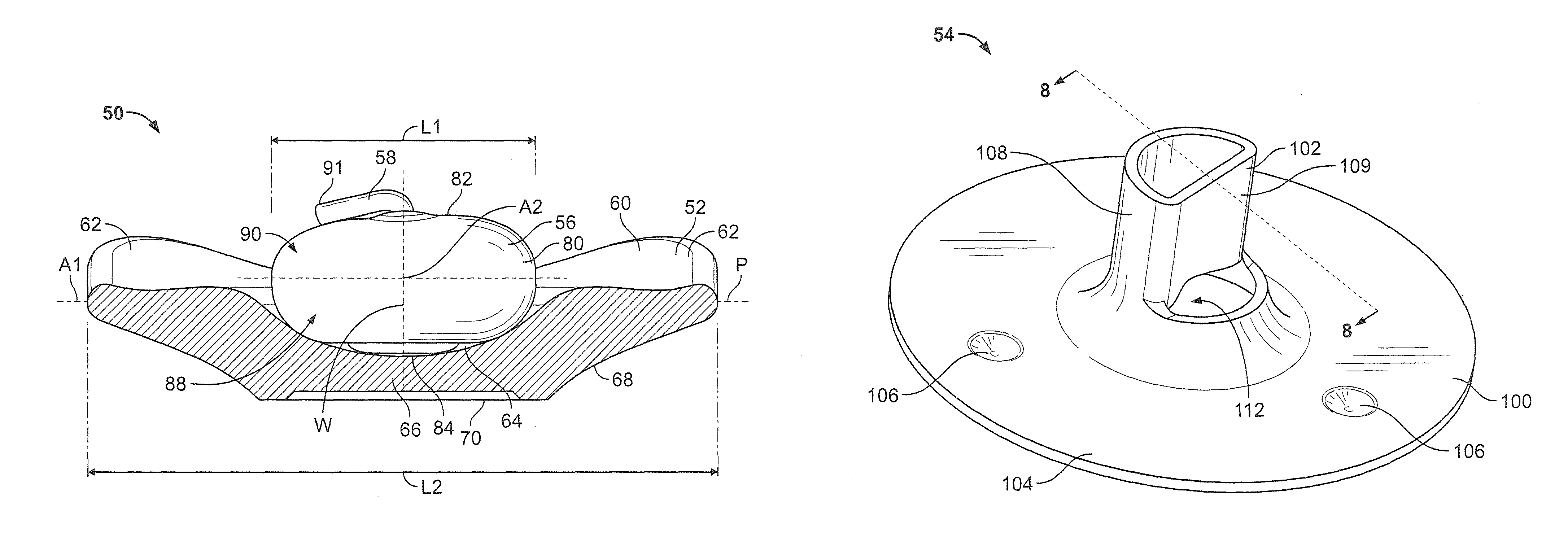
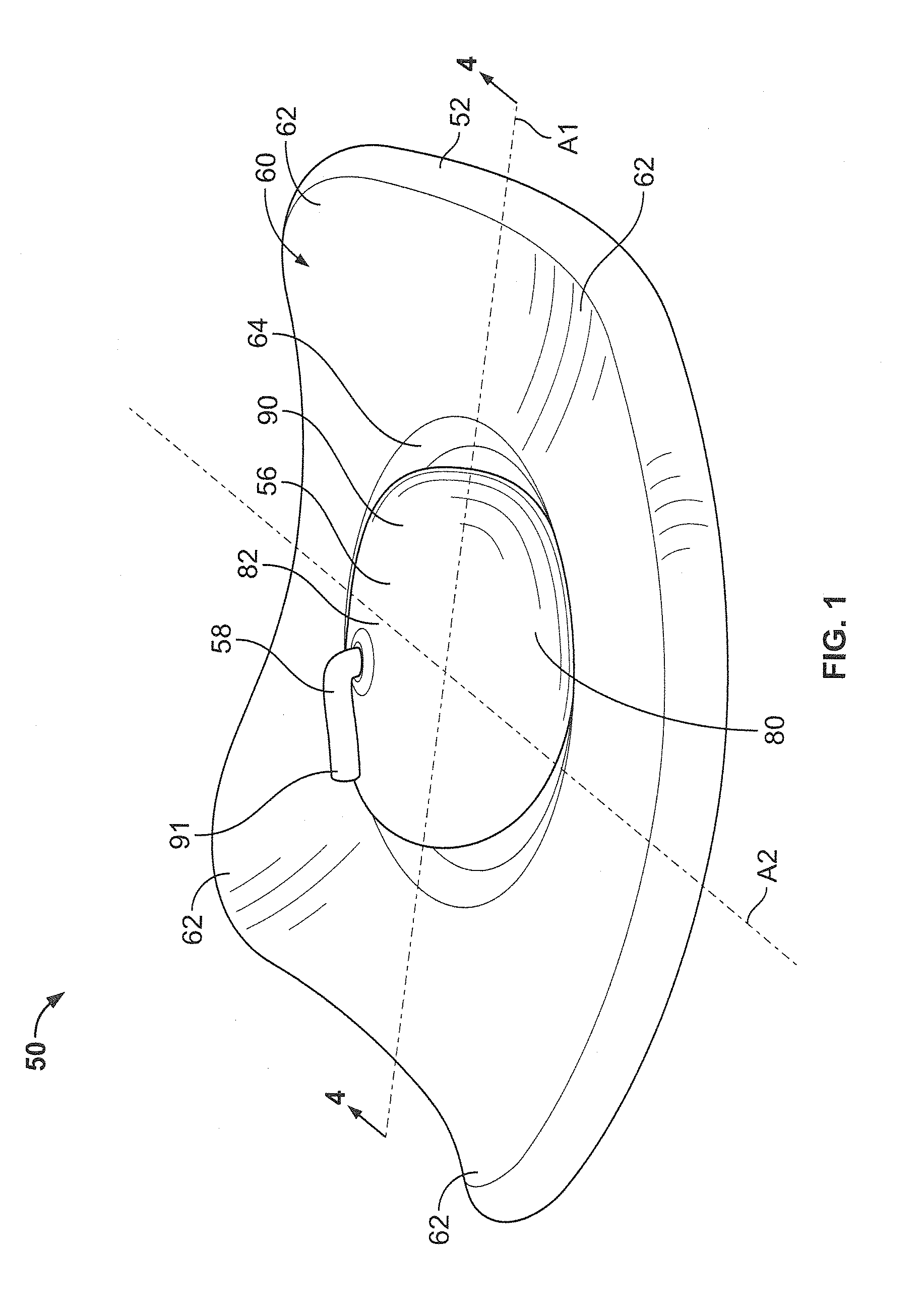
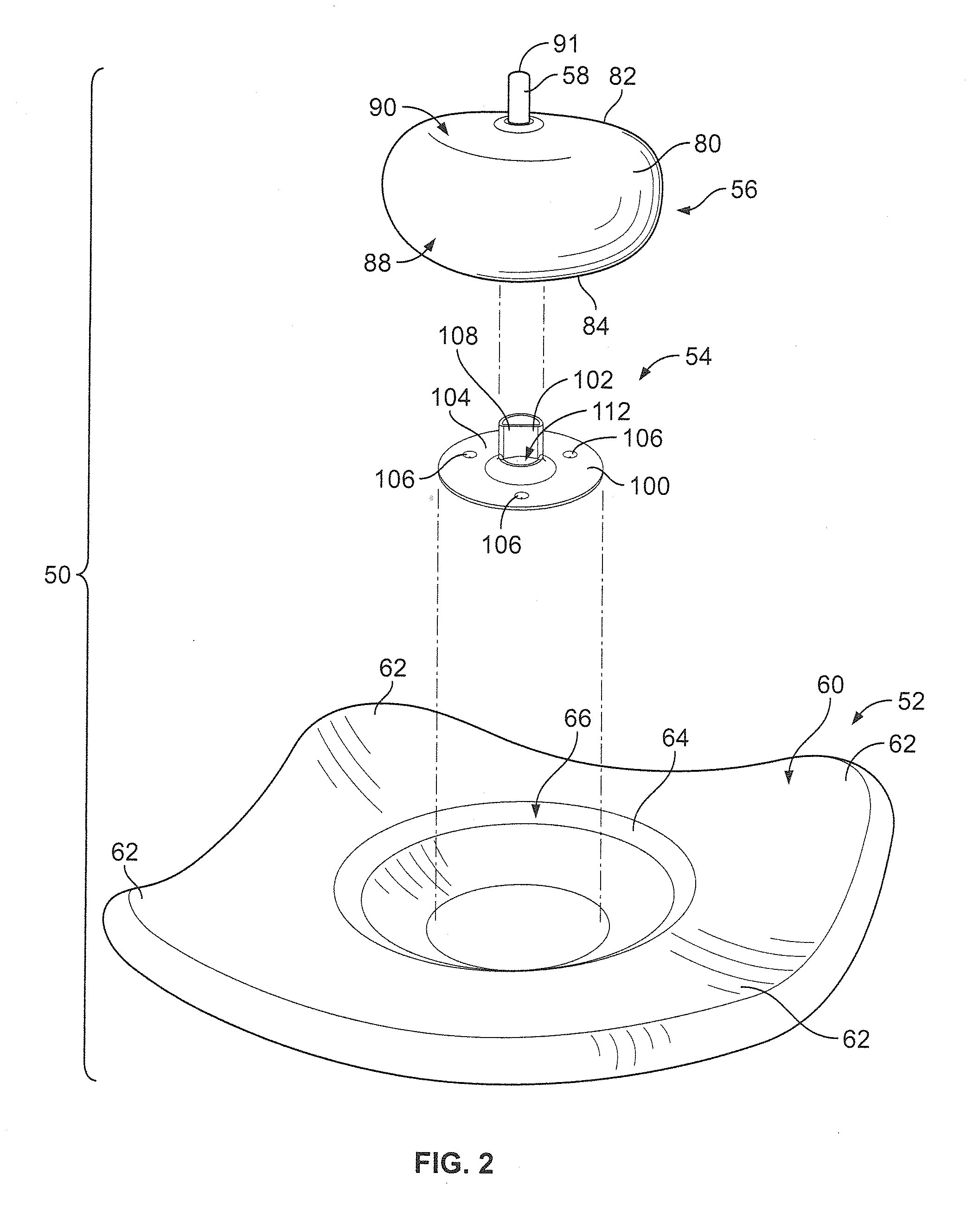
[0023]The present invention is directed to candle assemblies for melting fuel elements and dispensing volatile materials contained therein. While the present invention may be embodied in many different forms, several specific embodiments are discussed herein with the understanding that the present invention is to be considered only as an exemplification of the principles of the invention, and it is not intended to limit the invention to the embodiments illustrated.

[0024]Further, although the fuel element may be described as having a fragrance embedded therein for dispersion thereof, the fuel element may include any volatile material that a consumer may desire to emit into an area surrounding the candle assembly. Illustratively, the types of volatile materials may be, for example, an insecticide, an insect repellant, an insect attractant, a fragrance, an aromatherapy scent, a positive fragrancing volatile material, an air-freshener, a deodorizer, or the like, and combinations thereof...


PUM


Abstract

A candle assembly comprises a fuel element having a first surface, a second surface disposed opposite the first surface, and a channel extending through the fuel element from the first surface to the second surface. A support structure is adapted to support the first surface of the fuel element within a central portion of the support structure. A wick retainer has a flat portion with a centralized conduit extending outwardly from a top surface of the flat portion. A wick has a first end disposed within the wick retainer, wherein the wick and wick retainer are embedded in the fuel element prior to use such that a second end of the wick extends outwardly beyond the second surface of the fuel element.

Description

CROSS REFERENCE TO RELATED APPLICATIONS[0001]Not Applicable.REFERENCE REGARDING FEDERALLY SPONSORED RESEARCH OR DEVELOPMENT[0002]Not applicableSEQUENTIAL LISTING[0003]Not applicableBACKGROUND OF THE INVENTION[0004]1. Field of the Invention[0005]The present invention relates generally to candle assemblies, and more specifically to candle assemblies having a fuel element, a wick, and a wick retainer.[0006]2. Description of the Background of the Invention[0007]Candles and candle assemblies of all types are known in the art and have generally been focused on different varieties of votive candles, pillar candles, deep drawn candles, and melting plate candles. Some candle assemblies include a support structure or container to hold the candle wax, a wick, and optionally include a wick retainer that locates and secures the wick thereto.[0008]More recently, melting plate candles and simmer plates have been used to provide rapid melting of a solid fuel element and / or rapid dispensing of a vap...

Claims


Application Information

Patent Timeline
Patent Type & Authority Patents(United States)
IPC IPC(8): F23D3/16
CPCF23D3/16F23D3/24C11C5/006C11C5/008A61J9/00A61M39/10A61M39/20A61M2205/0216A61M2210/1007A61M1/064
Inventor CRAPSER, JAMES R.HELF, THOMAS A.MIKIC, TOMMY
Owner SC JOHNSON & SON INC
Why Eureka
Try Eureka