
Eureka
For R&D, Eureka makes reading and utilizing patents & technical documents easy.
Eureka AIR
Designed for self-driven R&D workflows. Generate viable solutions, solve complex R&D challenges, empower your innovation with AI.

Eureka Materials
Designed for material experts only. Revolutionize your material R&D, from search, analyze, to developing new materials.

TechResearch
Generate reliable direction feasibility study reports for your R&D in just a few steps.

TechSeek
Discover and master advanced knowledge NOW. Basics, ideas, possibilities, all at once.

TechMind
As an expert in R&D Theories, TechMind can generates customized viable solutions instantly.

TechRisk
Analyze your overall solution with one click, know your potential R&D risks in advance.

TechMonitor
Get weekly tech updates, stay abreast of the latest tech innovations and key insights.
Adjustable-depth ring assembly and method of installation
- Summary
- Abstract
- Description
- Claims
- Application Information
AI Technical Summary
Benefits of technology
Problems solved by technology
Method used
Image

Examples
first embodiment
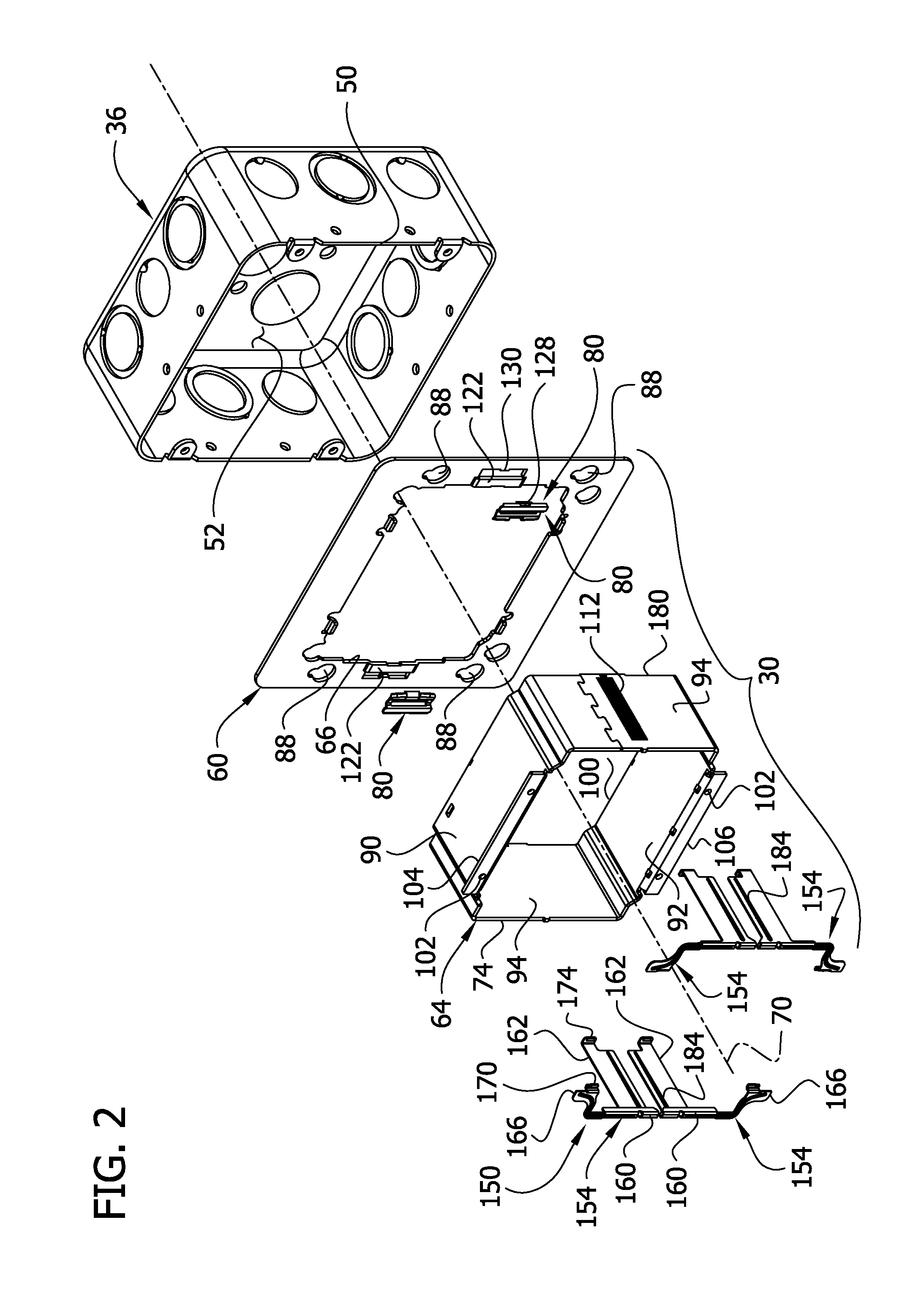
[0039]In FIGS. 1-14, the box cover plate 60 is a flat generally planar rigid plate of suitable material (e.g., metal) having conventional fastener openings 88 around its periphery for receiving fasteners to fasten the box cover plate to the electrical box 36. The number, shape and configuration of these openings 88 can vary. The central opening 66 in the box cover plate 60 has a shape (e.g., rectangular, round, or octagonal) and size that generally match the opening 50 at the front of the electrical box 36. It will be understood in this regard that the box cover plate 60 can be sized for one electrical device or multiple electrical devices (e.g., two, three, four or more) depending on the size and wiring configuration of the electrical box 36.
[0040]The extension ring 64 is substantially rigid and of suitable material such as metal (e.g., galvanized steel). The ring 64 has top, bottom and side walls 90, 92, 94 extending rearward from the front 74 of the ring. The walls define a gener...
second embodiment
[0051]FIGS. 15 and 16 illustrate an adjustable-depth ring assembly of this invention, generally designated 300. In general, the assembly 300 comprises (i) an extension ring 304 sized for reception in a central opening 306 of a box cover plate 310 (FIG. 17) attached to an electrical box 320, (ii) an electrical device or devices 324 received in a cavity 328 defined by the extension ring, and (iii) a finish cover plate 330 attached by suitable fasteners 334 to the electrical device(s) at a location in front of the extension ring. The extension ring 304, electrical device(s) 324 and finish cover plate 330 are fastened together to form a pre-assembled unit (also designated by the reference number 300). The unit is free of any connection with the box cover plate 310 and electrical box 320 prior to field installation, as will be described. The parts of the pre-assembled unit 300 will typically (but not necessarily) be assembled at a location remote from the job site, desirably at a time on...
third embodiment
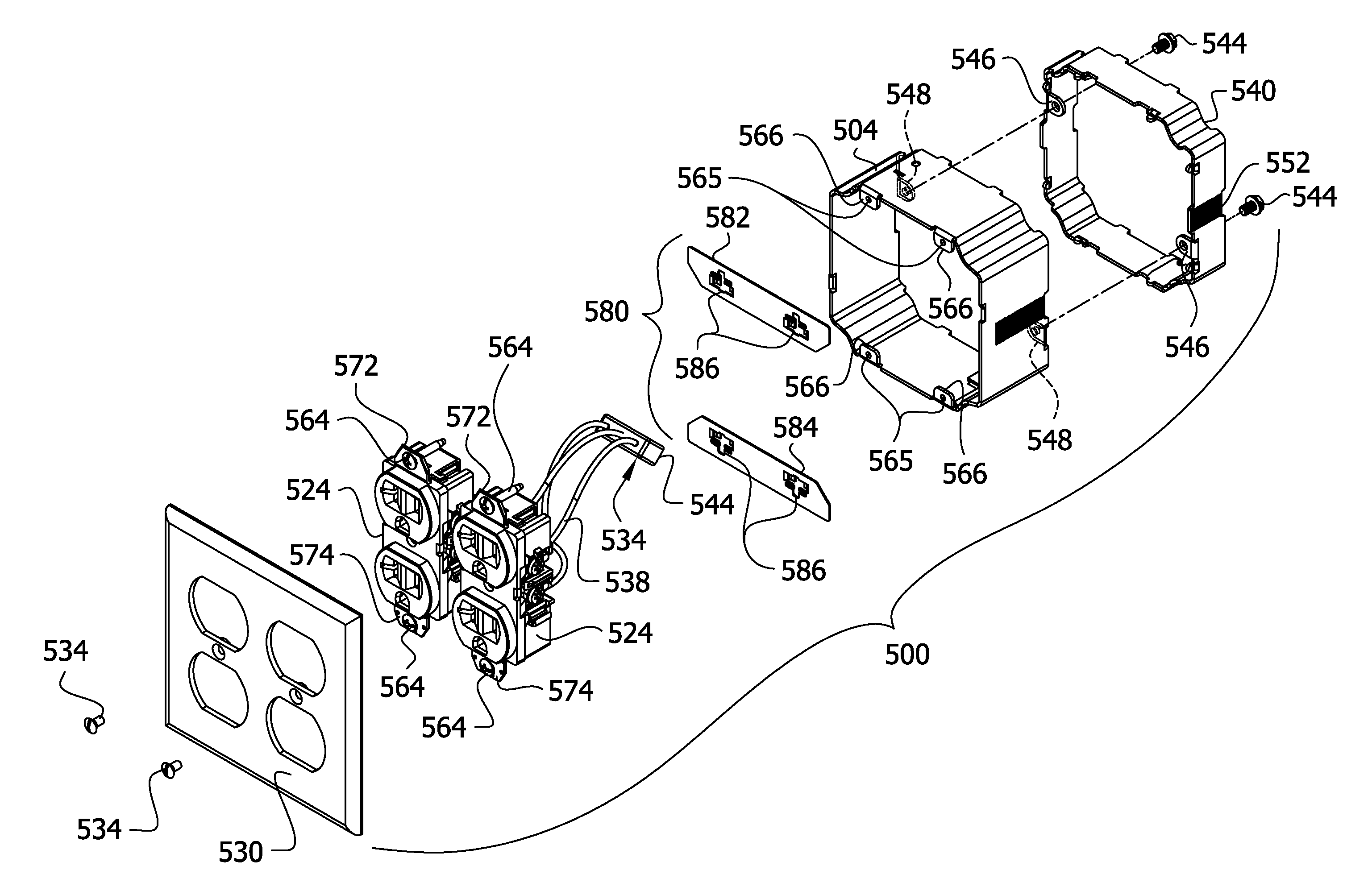
[0058]FIGS. 16A-16D illustrates an adjustable-depth ring assembly of this invention, generally designated 500. In general, the assembly 500 comprises (i) an extension ring 504 sized for reception in a central opening 506 of a box cover plate 310 (FIG. 17) attached to an electrical box 320, (ii) an electrical device or devices 524 received in a cavity 528 defined by the extension ring, and (iii) a finish cover plate 530 attached by suitable fasteners 534 to the electrical device(s) at a location in front of the extension ring. The extension ring 504, electrical device(s) 524 and finish cover plate 530 are fastened together to form a pre-assembled unit (also designated by the reference number 500). The unit is free of any connection with the box cover plate 310 and electrical box 320 prior to field installation, as will be described. The parts of the pre-assembled unit 500 will typically (but not necessarily) be assembled at a location remote from the job site, desirably at a time onl...
PUM
 Abstract
Description
Claims
Application Information
 - R&D Engineer
- R&D Manager
- IP Professional
- Industry Leading Data Capabilities
- Powerful AI technology
- Patent DNA Extraction
Browse by: Latest US Patents, China's latest patents, Technical Efficacy Thesaurus, Application Domain, Technology Topic, Popular Technical Reports.
© 2024 PatSnap. All rights reserved.Legal|Privacy policy|Modern Slavery Act Transparency Statement|Sitemap|About US| Contact US: help@patsnap.com