Brake structure of rotary table
a rotary table and brake technology, applied in the field of brake structure, can solve the problems of insufficient contact area between the thin wall and the inner peripheral surface, and the inability to securely clamp the rotatable table, and achieve the effect of thinning the rotary tabl
- Summary
- Abstract
- Description
- Claims
- Application Information
AI Technical Summary
Benefits of technology
Problems solved by technology
Method used
Image
Examples
Embodiment Construction
[0018]An embodiment of the present invention will be described in detail below by referring to the drawings.
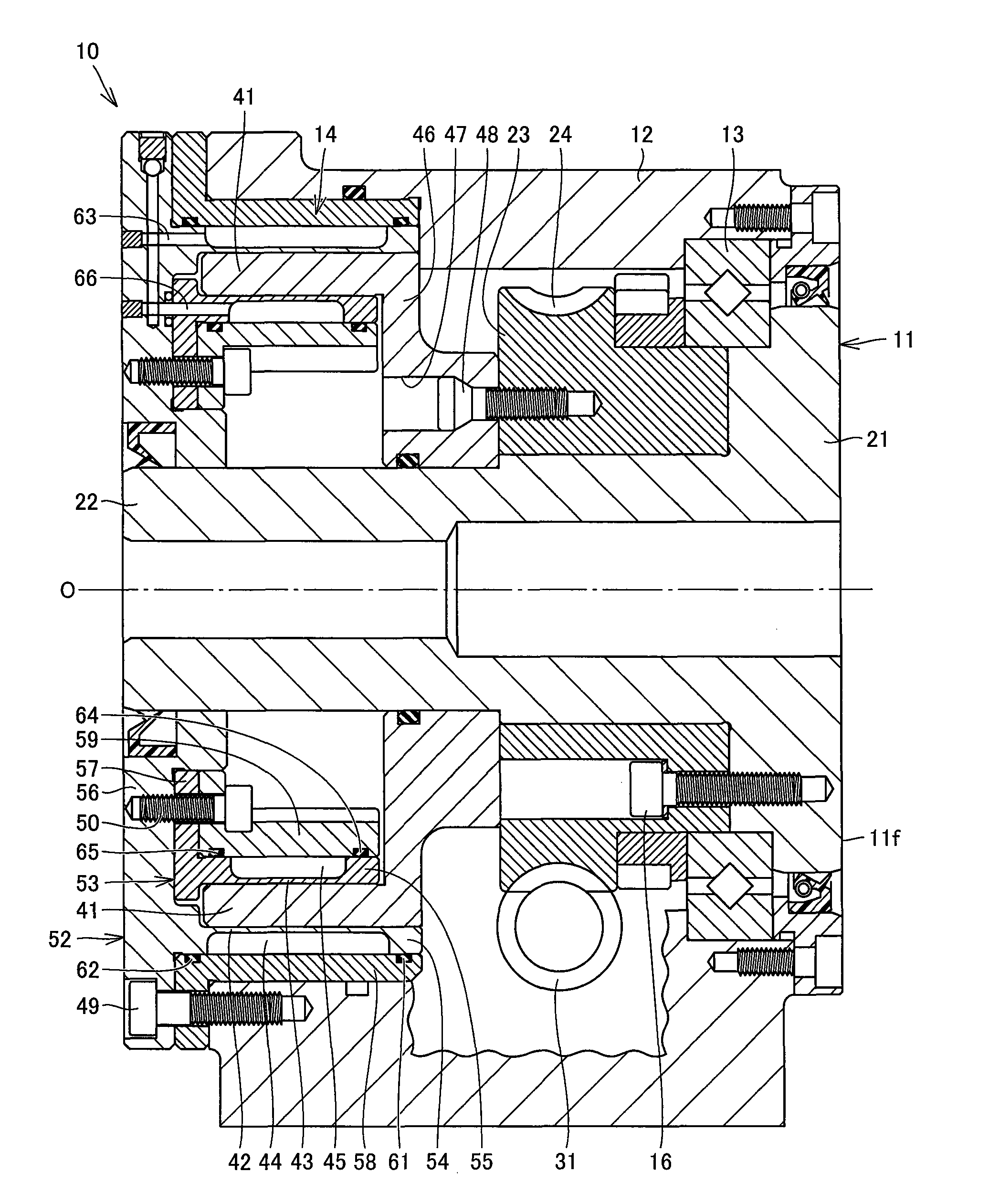
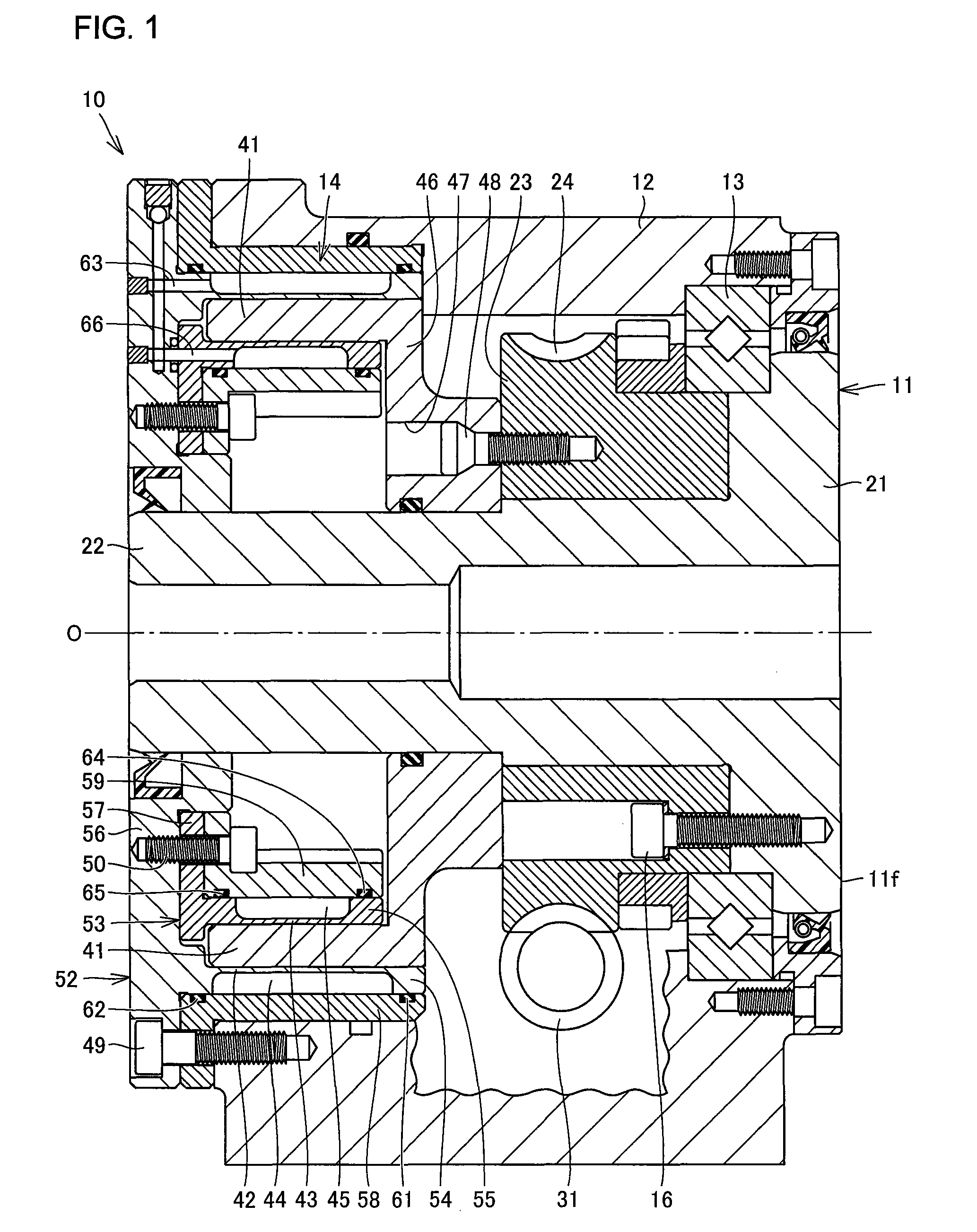
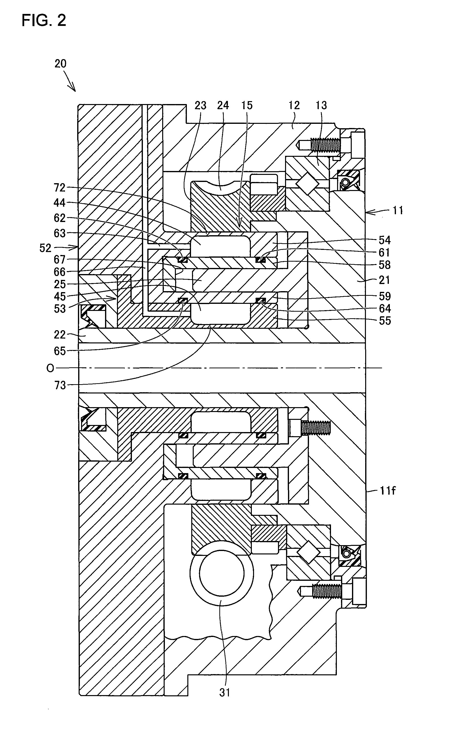
[0019]FIG. 1 is a vertical cross-sectional view showing a brake structure of a rotary table according to the embodiment of the present invention. A rotary table 10 includes a rotatable table 11, a housing 12, a bearing 13 provided between the rotatable table 11 and housing 12, and a brake mechanism 14 provided between the rotatable table 11 and housing 12.
[0020]The rotatable table 11 rotates about an axis O indicated by a dashed dotted line in FIG. 1. The rotatable table 11 has a disc-like table portion 21. The table portion 21 has a front surface 11f orthogonal to the axis O to support a workpiece or other machine tools thereon. The rotatable table 11 also has a shaft portion 22 extending from a back surface of the table portion 21 along the axis O.
[0021]An annular member 23 is coaxially secured to the back surface of the table portion 21 with bolts 16. The annular member 23 ...
PUM
 Abstract
Description
Claims
Application Information
 - R&D
- Intellectual Property
- Life Sciences
- Materials
- Tech Scout
- Unparalleled Data Quality
- Higher Quality Content
- 60% Fewer Hallucinations
Browse by: Latest US Patents, China's latest patents, Technical Efficacy Thesaurus, Application Domain, Technology Topic, Popular Technical Reports.
© 2025 PatSnap. All rights reserved.Legal|Privacy policy|Modern Slavery Act Transparency Statement|Sitemap|About US| Contact US: help@patsnap.com


