Brake Structure of Rotary Table

a rotary table and brake technology, applied in the direction of hydraulic brakes, hydraulic drum brakes, hoisting equipment, etc., can solve the problems of insufficient contact area between the thin wall and the inner peripheral surface, and the inability to securely clamp the rotatable table, etc., to achieve the effect of thinning the rotary tabl

Active Publication Date: 2013-05-02
NIKKEN KOSAKUSHO WORKS LTD
View PDF0 Cites 10 Cited by
  • Summary
  • Abstract
  • Description
  • Claims
  • Application Information

AI Technical Summary

Benefits of technology

[0013]The driving source of the rotatable table is not specifically limited. In an embodiment, the rotatable table can be directly rotated by a drive motor without a reduction mechanism. In another embodiment, the rotatable table can be rotatably driven with a reduction mechanism disposed between the rotatable table and the driving source. The reduction mechanism may be, for example, a worm gear. The worm gear includes a worm wheel coaxially secured to the rotatable table and a worm (screw gear) meshed with the worm wheel. The worm wheel can be placed away from the outer peripheral surface and inner peripheral surface, which are clamped portions, in the axial direction. Alternatively, the worm wheel can be placed so that the axial position of the worm wheel coincides with the axial position of the outer peripheral surface or inner peripheral surface, both of which are clamped portions. In an embodiment, a worm wheel is formed on the outer peripheral surface of the annular member. According to the embodiment, at least one part of the axial position of the worm wheel coincides with the axial position of the inner peripheral surface formed on the rotatable table, thereby shortening the rotary table in the axial direction and making the rotary table thinner.
[0014]In an embodiment, the outer stationary portion and inner stationary portion are separated by a circumferential groove, and the rotatable table is provided with a tubular portion that fits in the circumferential groove. According to the embodiment, the tubular portion interposed between the outer stationary portion and inner stationary portion prevents the outer stationary portion from tilting radially inward and prevents the inner stationary portion from tilting radially outward to clamp the rotatable table.

Problems solved by technology

Especially if a sleeve has a small inner diameter, the inner peripheral surface area of the sleeve is naturally small, which cannot secure a sufficient contact area between the thin wall and the inner peripheral surface of the sleeve.
As a result, the rotatable table cannot be securely clamped.

Method used


Image

  • Brake Structure of Rotary Table
  • Brake Structure of Rotary Table
  • Brake Structure of Rotary Table

Examples


Embodiment Construction

[0018]An embodiment of the present invention will be described in detail below by referring to the drawings.

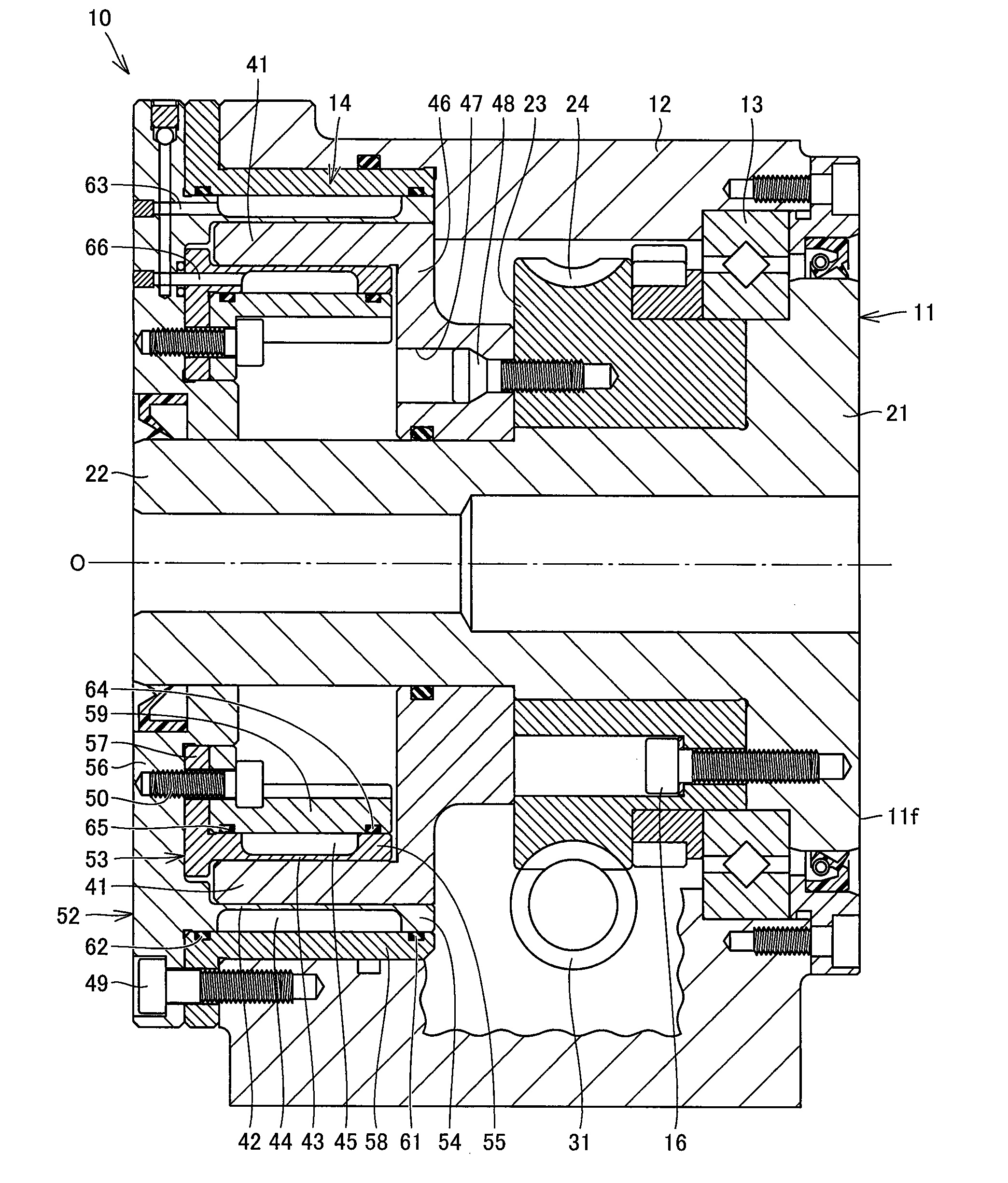
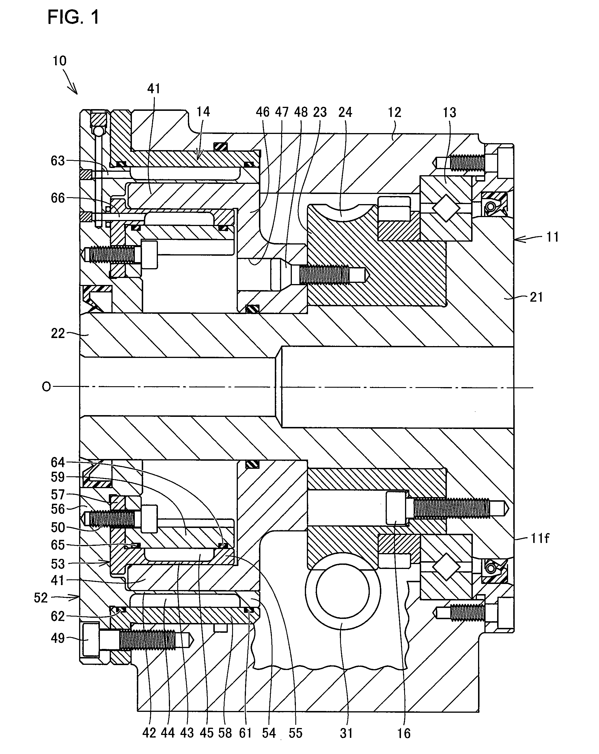
[0019]FIG. 1 is a vertical cross-sectional view showing a brake structure of a rotary table according to the embodiment of the present invention. A rotary table 10 includes a rotatable table 11, a housing 12, a bearing 13 provided between the rotatable table 11 and housing 12, and a brake mechanism 14 provided between the rotatable table 11 and housing 12.

[0020]The rotatable table 11 rotates about an axis O indicated by a dashed dotted line in FIG. 1. The rotatable table 11 has a disc-like table portion 21. The table portion 21 has a front surface 11f orthogonal to the axis O to support a workpiece or other machine tools thereon. The rotatable table 11 also has a shaft portion 22 extending from a back surface of the table portion 21 along the axis O.

[0021]An annular member 23 is coaxially secured to the back surface of the table portion 21 with bolts 16. The annular member 23 ...


PUM


Abstract

A rotary table includes a brake mechanism capable of providing a large and sufficient brake force. The brake mechanism includes an inner peripheral surface and outer peripheral surface of a sleeve formed coaxially with an axis of a rotatable table, an outer stationary portion provided to a stationary member rotatably supporting the rotatable table and defining an outer hydraulic chamber, and an inner stationary portion provided to the stationary member, arranged radially inward from the outer stationary portion and defining an inner hydraulic chamber. The outer stationary portion is elastically deformed in a radial direction by expansion of the outer hydraulic chamber to push the outer peripheral surface of the sleeve formed on the rotatable table, while the inner stationary portion is elastically deformed in a radial direction by expansion of the inner hydraulic chamber to push the inner peripheral surface of the sleeve formed on the rotatable table.

Description

BACKGROUND OF THE INVENTION[0001]1. Field of the Invention[0002]The present invention relates to a rotary table with a rotatable table, and more particularly to a brake structure, for a rotary table, that clamps a rotatable table to stop the rotation of the rotatable table.[0003]2. Description of the Related Art[0004]A general rotary table includes a rotatable index table, a stationary member (main body) rotatably supporting the rotatable table, a driving mechanism driving the rotatable table, and a brake mechanism clamping the rotatable table so as not to rotate the rotatable table. An example of the brake mechanism is disclosed in Japanese Unexamined Patent Application Publication No. 2009-248244 (FIG. 1). This brake mechanism includes a cylindrical sleeve coaxially provided on the back surface of the rotatable table and a hydraulic chamber formed on the non-rotatable stationary member that faces the inner peripheral surface of the sleeve. Feeding oil into and applying pressure on...

Claims


Application Information

Patent Timeline
Patent Type & Authority Applications(United States)
IPC IPC(8): F16D51/00
CPCB23Q16/107B23Q1/287
Inventor YOSHIMOTO, HIROHARUMATSUMOTO, JUN
Owner NIKKEN KOSAKUSHO WORKS LTD
Why Eureka
Try Eureka