

Energy harvesting seating
a technology of energy harvesting and seating, which is applied in the direction of chairs, electric generator control, machines/engines, etc., can solve the problem that the resistance offered by the mechanism is relatively unnoticeable to the user, and achieve the effect of reducing or even eliminating the need for separate power cables and connectors
- Summary
- Abstract
- Description
- Claims
- Application Information
AI Technical Summary
Benefits of technology
Problems solved by technology
Method used
Image

Examples
first embodiment
I. First Embodiment
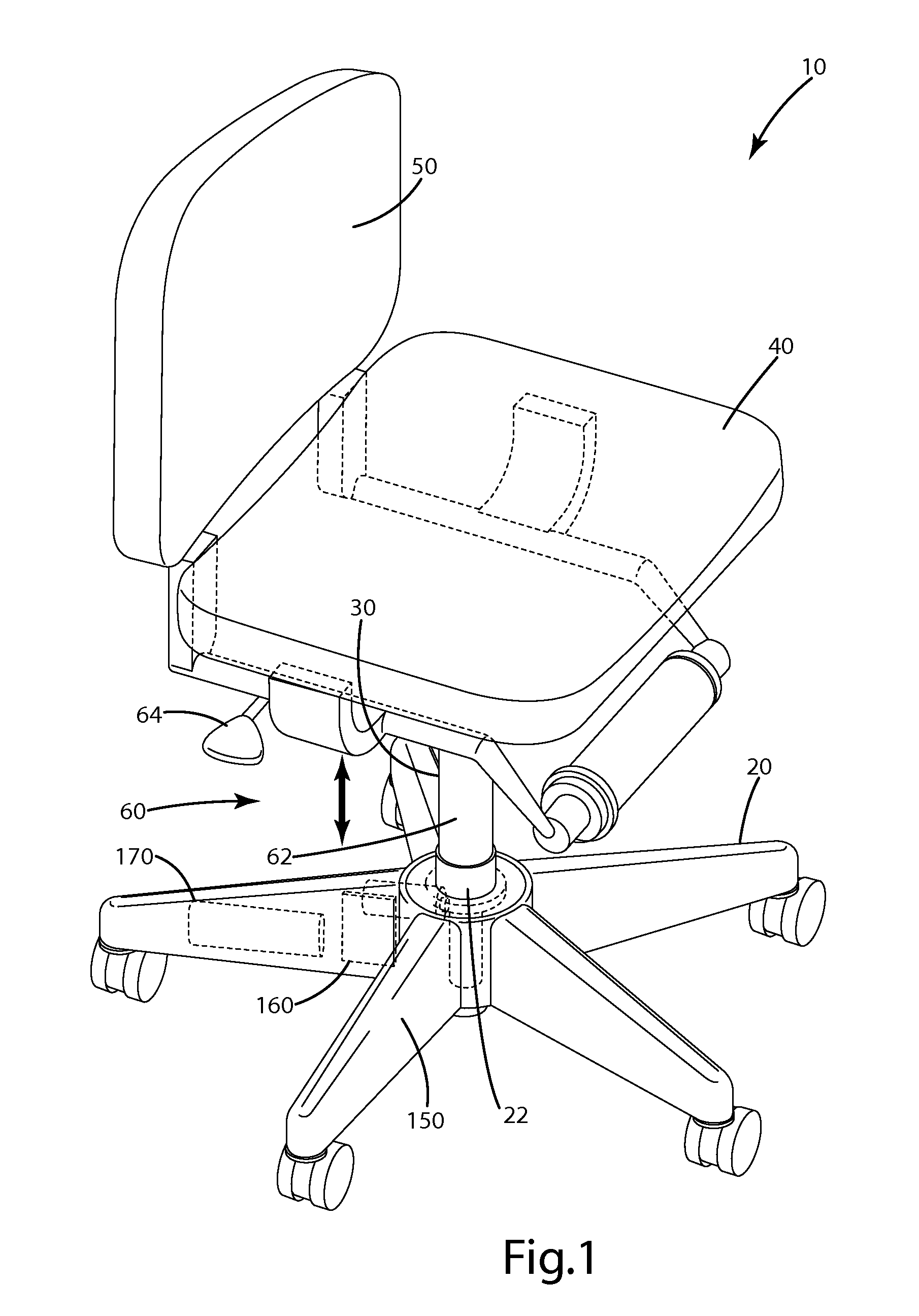
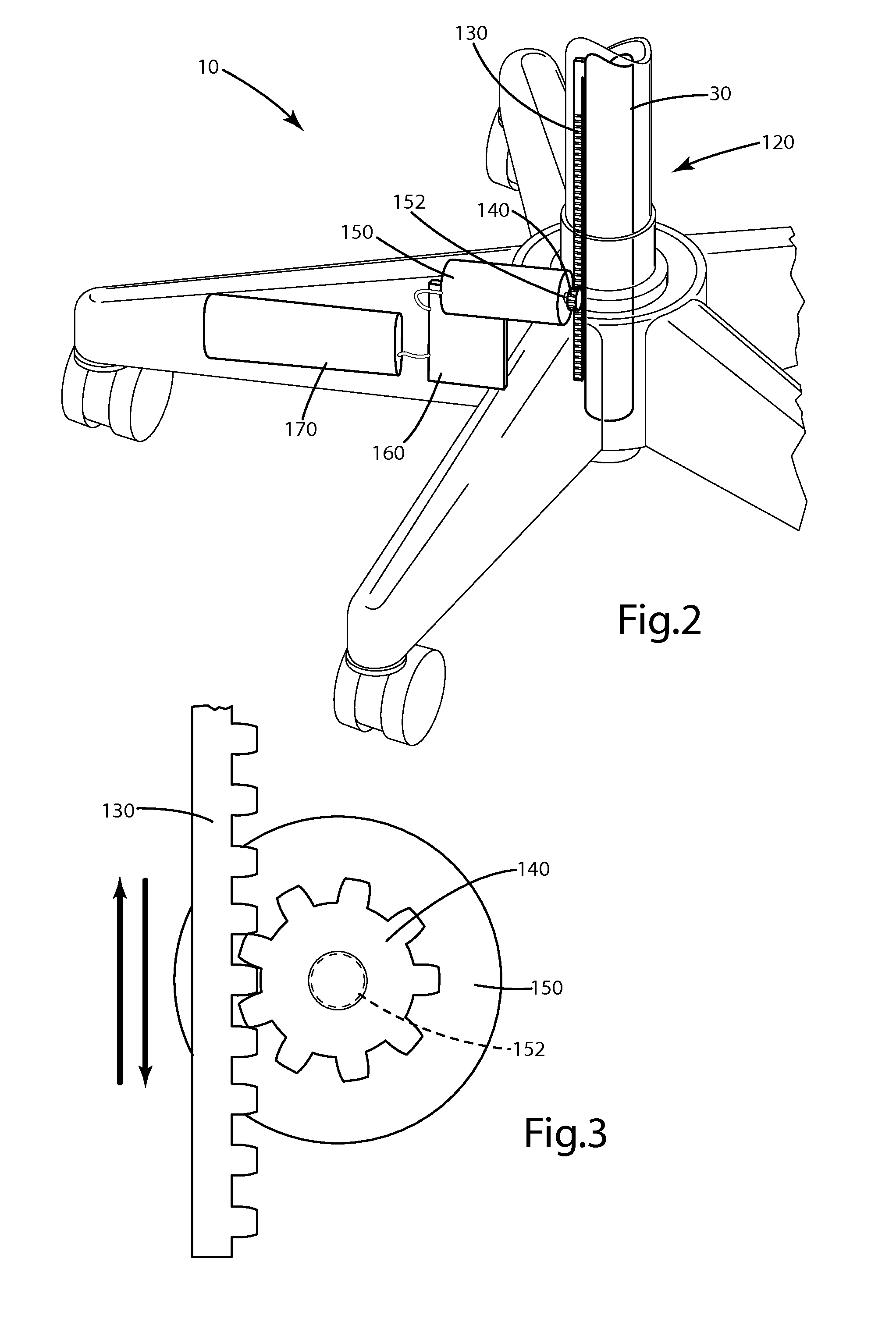
[0025]An energy harvesting seating system constructed in accordance with a first embodiment of the present invention is illustrated in FIGS. 1-3 and generally designated 10. The seating system includes a plurality of legs 20 and a seating article, including a seat 40 and a seat back 50. The legs 20 meet at a hub 22. A column 30 extends upward from the hub 22. Seat 40 moves vertically with column 30. Seat back 50 is attached to seat 40 and extends generally upward from seat 40. Seating system 10 includes a seat height adjustment mechanism 60. Seat height adjustment mechanism 60 includes a cylinder 62 within column 30 to move the seat upward relative to the legs 20 when a user previously sitting in seat 40 vacates seat 40. Cylinder 62 may be powered by a spring, pneumatic or hydraulic piston, or any other means suitable for the application. Optionally, a user may use handle 64 to activate cylinder 62 and set an initial height for seat 40.
[0026]Seating system 10 incl...
second embodiment
II. Second Embodiment
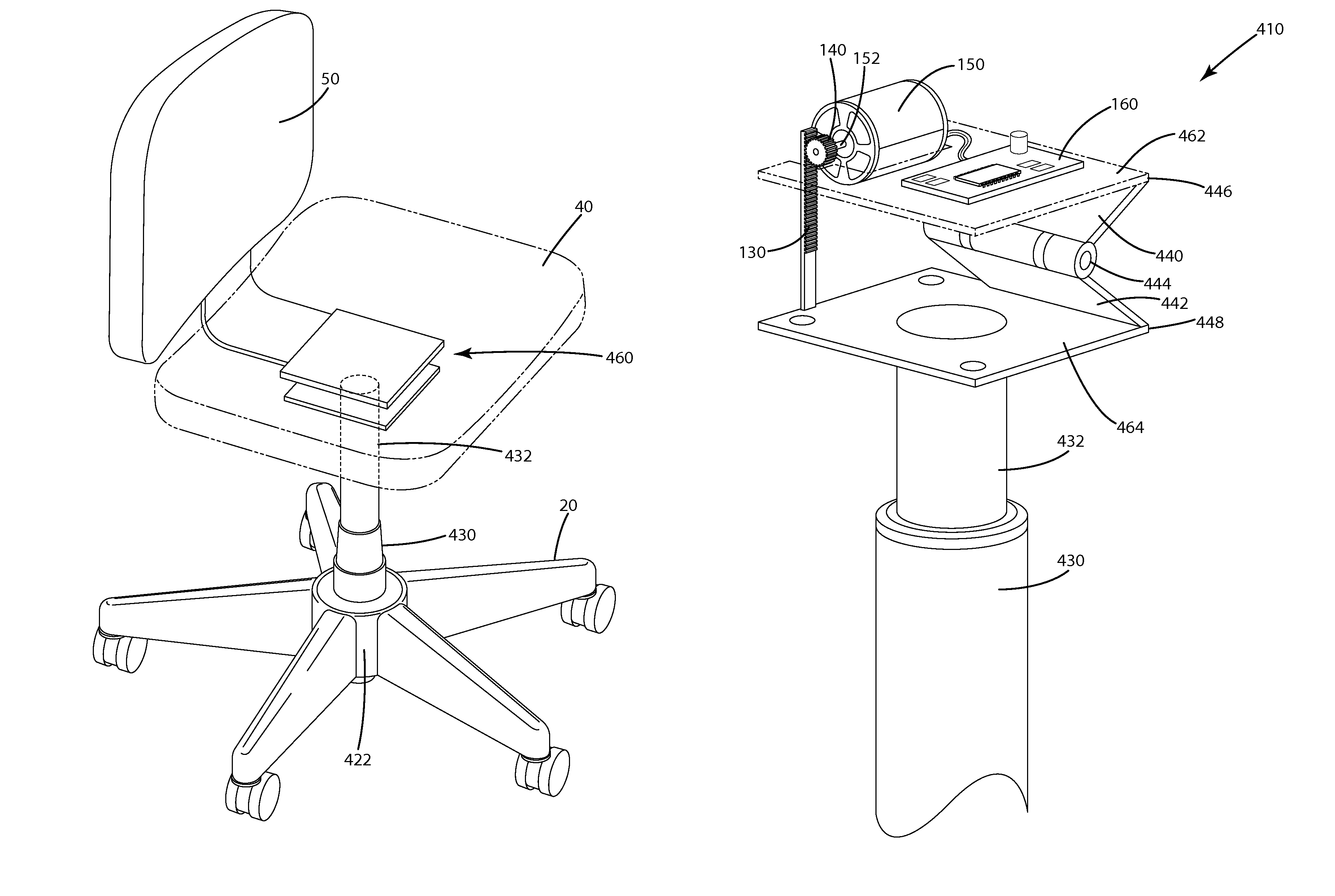
[0031]An illustration of a seating system is shown in FIG. 8. The seating system includes a plurality of legs 20 and a seating article, including a seat 40 and a seat back 50. The legs 20 meet at a hub 422. A telescoping midsection 430 extends upward from legs 20 through hub 422. A cylinder 432 extends upward through telescoping midsection 430 to adjust the height of the seat. Cylinder 432 may be powered manually or automatically by pneumatics, hydraulics, springs, or by any other means suitable to the application. Cylinder 432 may rotate within telescoping midsection 430. Seat back 50 is attached to seat 40 and extends generally upward from seat 40. An energy generation space 460 is located between seat 40 and cylinder 432 in which the upward and / or downward movements of the seat 40 are used to generate energy. Energy generation space 460 will be described in more detail with regard to the various embodiments.
[0032]An energy harvesting system constructed in acc...
third embodiment
III. Third Embodiment
[0036]An energy harvesting system constructed in accordance with a third embodiment of the present invention is illustrated in FIG. 10 and generally designated 510. Energy harvesting system 510 is located within energy generation space 460 and includes a top plate 562 and a bottom plate 564. Top plate 562 moves vertically with seat 40, and bottom plate 564 remains stationary while seat 40 moves vertically. For example, top plate 562 may be mounted to or supported by seat 40 and bottom plate 564 may be mounted to or supported by cylinder 432 such that top plate 562 moves in at least the vertical direction with seat 40 while bottom plate 564 remains stationary in at least the vertical direction. Energy harvesting system 510 includes two generators 150 mounted to bottom plate 564. A pinion gear 140 is rigidly attached to each generator 150 with a drive shaft 152. Pinion gears 140 align and interact with a drive gear or notched post 530, which is mounted to top plat...
PUM
 Abstract
Description
Claims
Application Information