
Easy assembling one click bulb socket

a bulb socket and one-click technology, applied in the direction of line/current collector details, electrical equipment, coupling device connections, etc., can solve the problems of difficult removal of bulbs, electrical shock hazards for users of sockets, and the removal of bulbs from sockets after the threaded bas

Active Publication Date: 2013-12-10
SANCHEZ ISAAC
View PDF13 Cites 5 Cited by
  • Summary
  • Abstract
  • Description
  • Claims
  • Application Information

AI Technical Summary

Benefits of technology

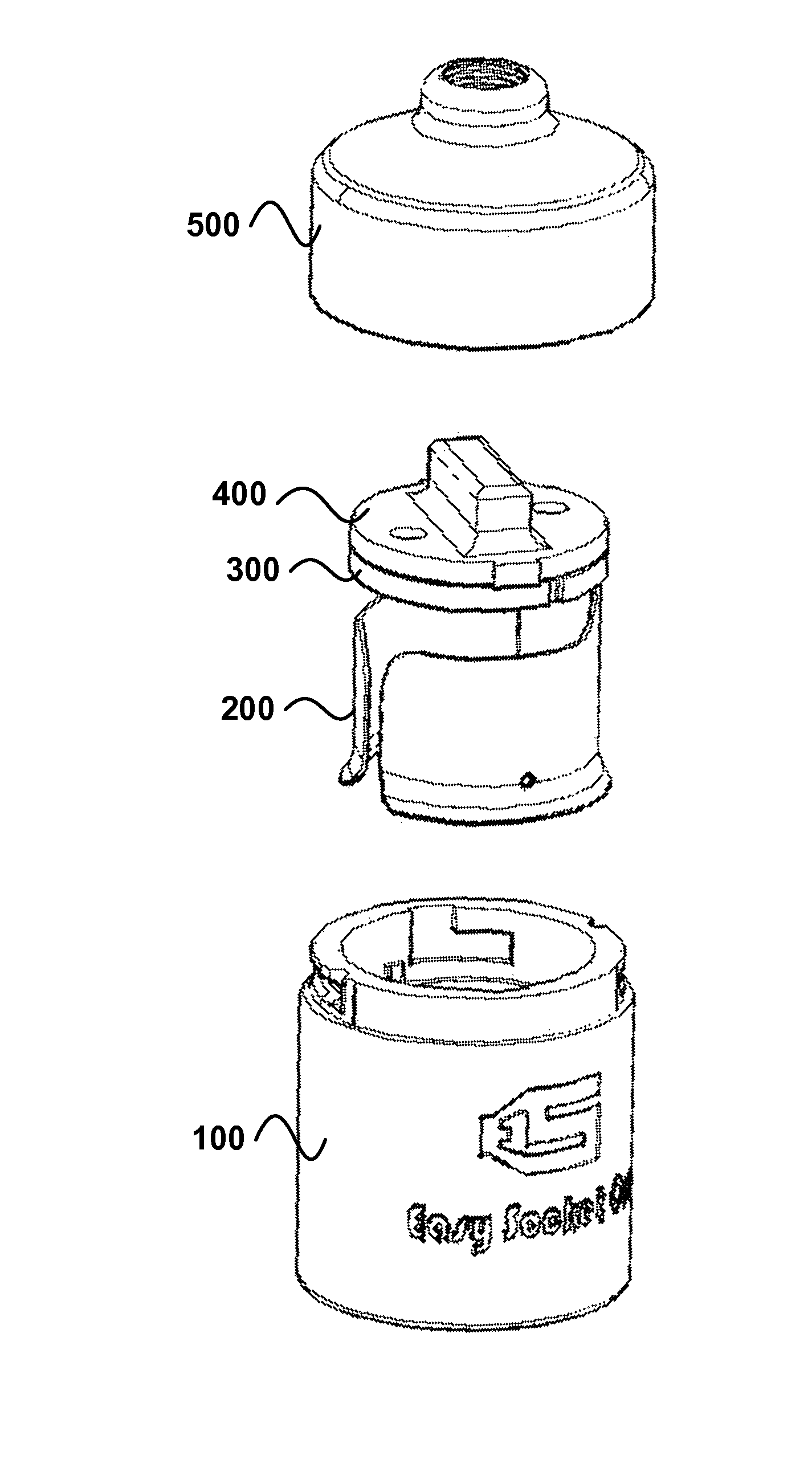
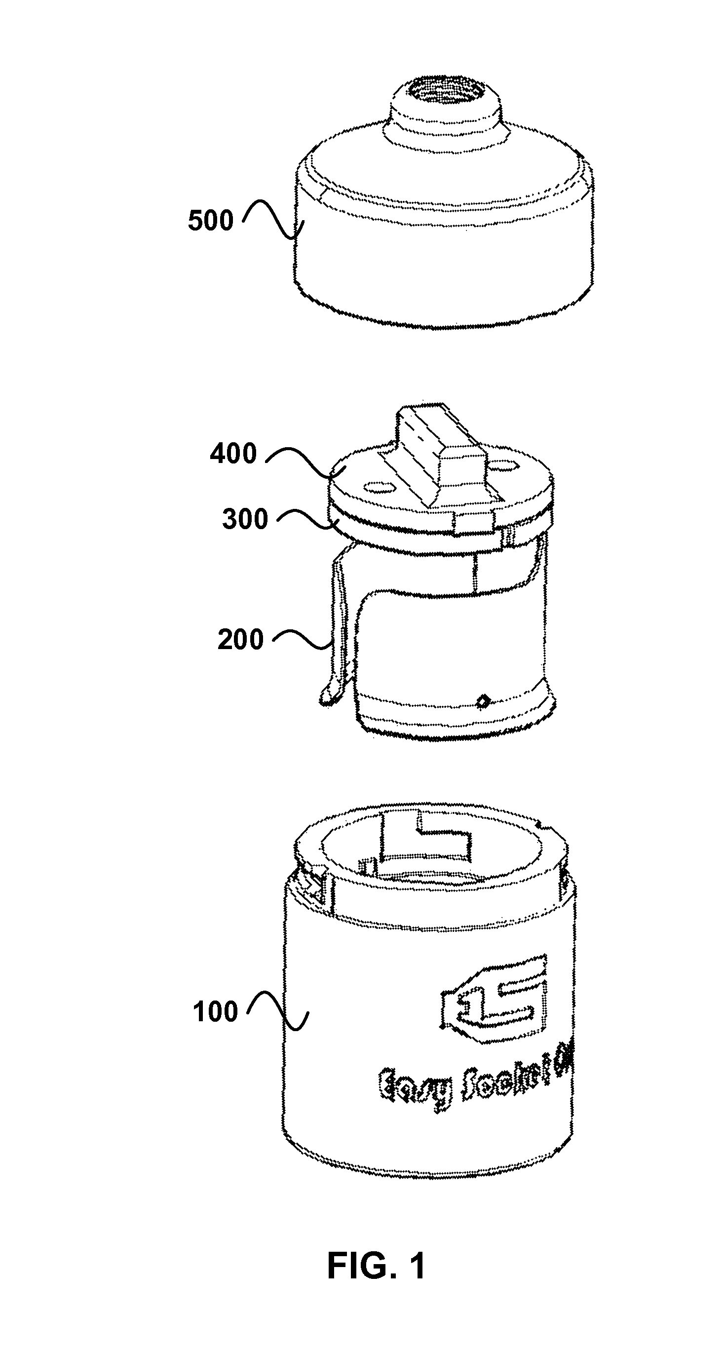
The disclosed light bulb socket is designed to securely hold and electrically connect a light bulb with a single clicking action. The socket comprises a conductive sleeve with two arms and a foot that secure the light bulb in place. The sleeve also has a rivet hole and a ribbon that secure wires for electrical connection. The socket can be easily assembled with a power cord and has a cap for securely connecting the light bulb. The method of assembly involves fitting a disk into the socket, threading the cord wires through the disks, and securing the wires between the disks with rivets and elliptical recesses. The technical benefits of this design are ease of assembly and secure electrical connection to the light bulb.

Problems solved by technology

Conventional threaded light bulb sockets for incandescent bulbs are notorious for difficult removal of the bulbs when over time a bulb may become jammed in the socket.
A light bulb may therefore break from the threaded base and present a electrical shock hazard to a user of the socket.
Removal of the bulb from the socket after the threaded base has broken from the glass globe can be dangerous if not annoying and problematic.
Also, it is not always easy or convenient to maintain bulbs in threaded light bulb sockets.
Hard to reach threaded sockets in high ceilings do not lend themselves to turning from below.
Large arrays of sockets present a serious cumulative time expenditure for unthreading and threading each one even if every socket is easily accessed.

Method used


Image

  • Easy assembling one click bulb socket
  • Easy assembling one click bulb socket
  • Easy assembling one click bulb socket

Examples


Embodiment Construction

[0029]Reference will now be made to exemplary embodiments illustrated in the drawings and specific language will be used herein to describe the same. It will nevertheless be understood that no limitation of the scope of the disclosure is thereby intended. Alterations and further modifications of the inventive features illustrated herein and additional applications of the principles of the inventions as illustrated herein, which would occur to one skilled in the relevant art and having possession of this disclosure, are to be considered within the scope of the invention.

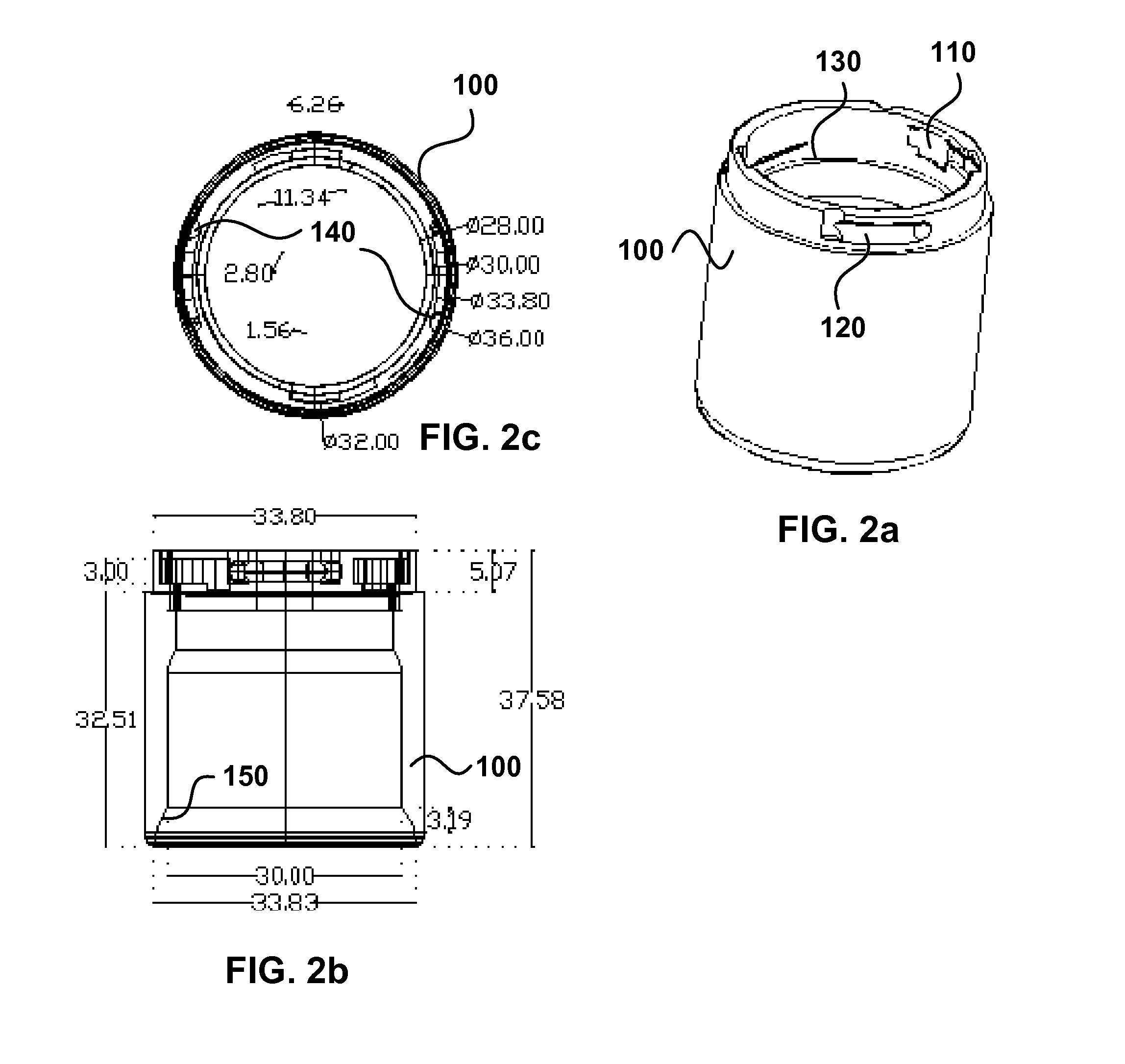
[0030]Embodiments of the disclosed easy assembling one click bulb socket and method for assembly may include all different types of lamp sockets accommodating different bulb sizes including a 26 mm, 27 mm, 12 mm and more. Lamp sockets with single throw switches and three way or multiple on / off switches are comprised in embodiments of the disclosure. Light sockets for ovens, refrigerators and other appliances may also ...


PUM

PropertyMeasurementUnit
inner diameteraaaaaaaaaa
sizesaaaaaaaaaa
sizesaaaaaaaaaa

Abstract

An easily assembling light bulb socket as disclosed secures a light bulb in a single clicking action. The disclosed socket comprises an electrically conductive sleeve configured to clasp a threaded end of the light bulb. The sleeve comprises a bump configured to slide into a thread recess and click-secure the bulb in the sleeve. A first disk received into the socket is riveted to the sleeve and to a metallic ribbon. The sleeve rivet makes a connection with a first wire and the ribbon rivet makes a connection with a second wire. The socket additionally comprises a second disk defining two holes aligned with the rivet holes in the first disk to receive a respective wire there through. The second disk holes include elliptical recesses configured to channel and secure the first and second wires between the disks when the second disk is axially rotated adjacent the first disk.

Description

CROSS-REFERENCE TO RELATED APPLICATION[0001]This application claims the benefit of the priority date of earlier filed U.S. Provisional Patent Application Ser. No. 61 / 463,437, filed Feb. 17, 2011 for Isaac Sanchez titled, Easy Socket One, incorporated herein by reference in its entirety.BACKGROUND OF THE INVENTION[0002]Conventional threaded light bulb sockets for incandescent bulbs are notorious for difficult removal of the bulbs when over time a bulb may become jammed in the socket. A light bulb may therefore break from the threaded base and present a electrical shock hazard to a user of the socket. Removal of the bulb from the socket after the threaded base has broken from the glass globe can be dangerous if not annoying and problematic.[0003]Also, it is not always easy or convenient to maintain bulbs in threaded light bulb sockets. Hard to reach threaded sockets in high ceilings do not lend themselves to turning from below. Large arrays of sockets present a serious cumulative time...

Claims


Application Information

Patent Timeline
Patent Type & Authority Patents(United States)
IPC IPC(8): H01R4/38
CPCH01R33/94Y10T29/49174
Inventor SANCHEZ, ISAAC
Owner SANCHEZ ISAAC
Learn More