
Syringe

a technology of syringe and syringe, which is applied in the field of syringe, can solve the problems of difficult to maintain the aseptic state inside the prefilled syringe, and the possibility of recapped prefilled syringes which are low in asepticity to be used, and achieve the effect of excellent tamperproofness

Active Publication Date: 2013-12-31
TERUMO KK
View PDF16 Cites 38 Cited by
  • Summary
  • Abstract
  • Description
  • Claims
  • Application Information

AI Technical Summary

Benefits of technology

The present invention provides a syringe that is designed to prevent unauthorized access.

Problems solved by technology

When the cap of a prefilled syringe is once opened, it is difficult to maintain the aseptic state inside the prefilled syringe for a long time, and, therefore, the liquid product needs to be used swiftly.
If recapping is done as above-mentioned, however, there has been a problem that the recapped prefilled syringe which is low in asepticity may be put to use, while erroneously deeming it as in the unused state.Patent Document 1: Japanese Laid-Open Patent Publication No. 2002-315827

Method used


Image

  • Syringe
  • Syringe
  • Syringe

Examples


Embodiment Construction

[0027]Now, a syringe according to the present invention will be described in detail below, based on a preferred embodiment shown in the accompanying drawings.

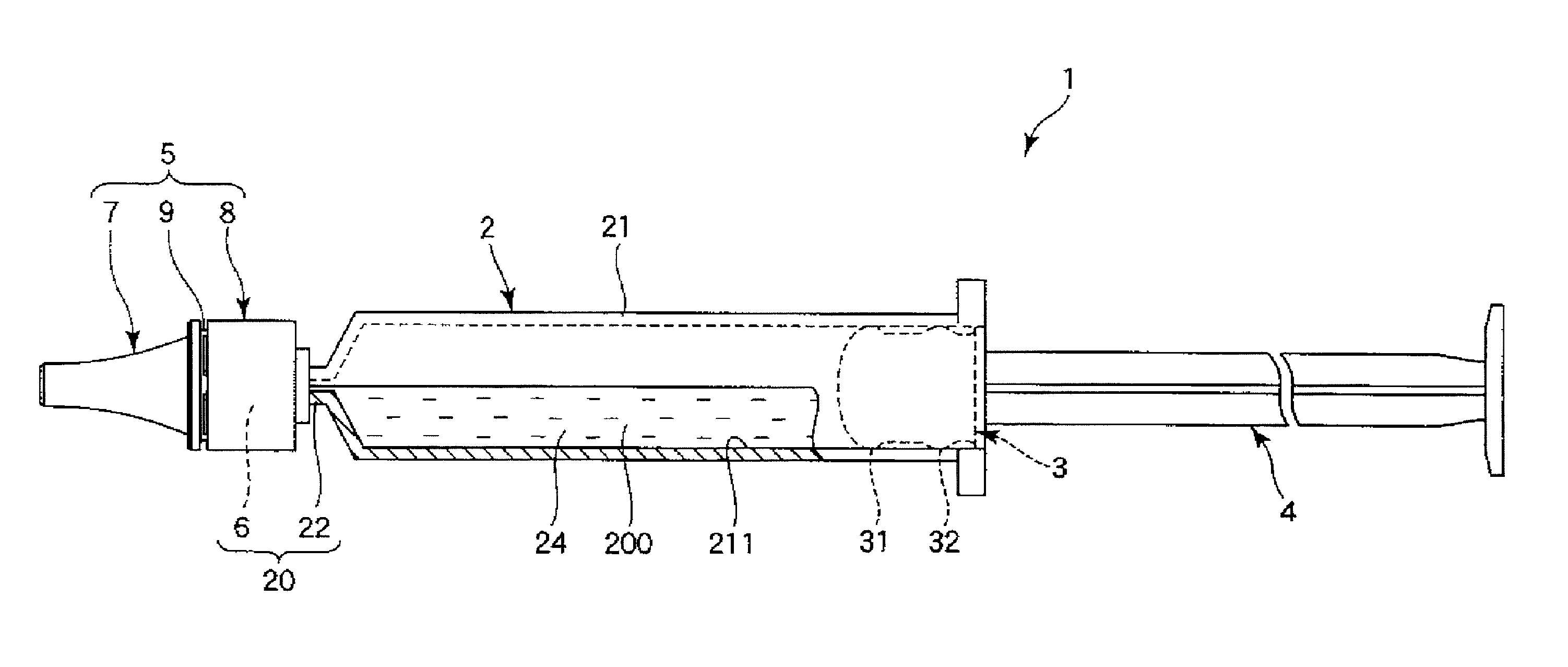
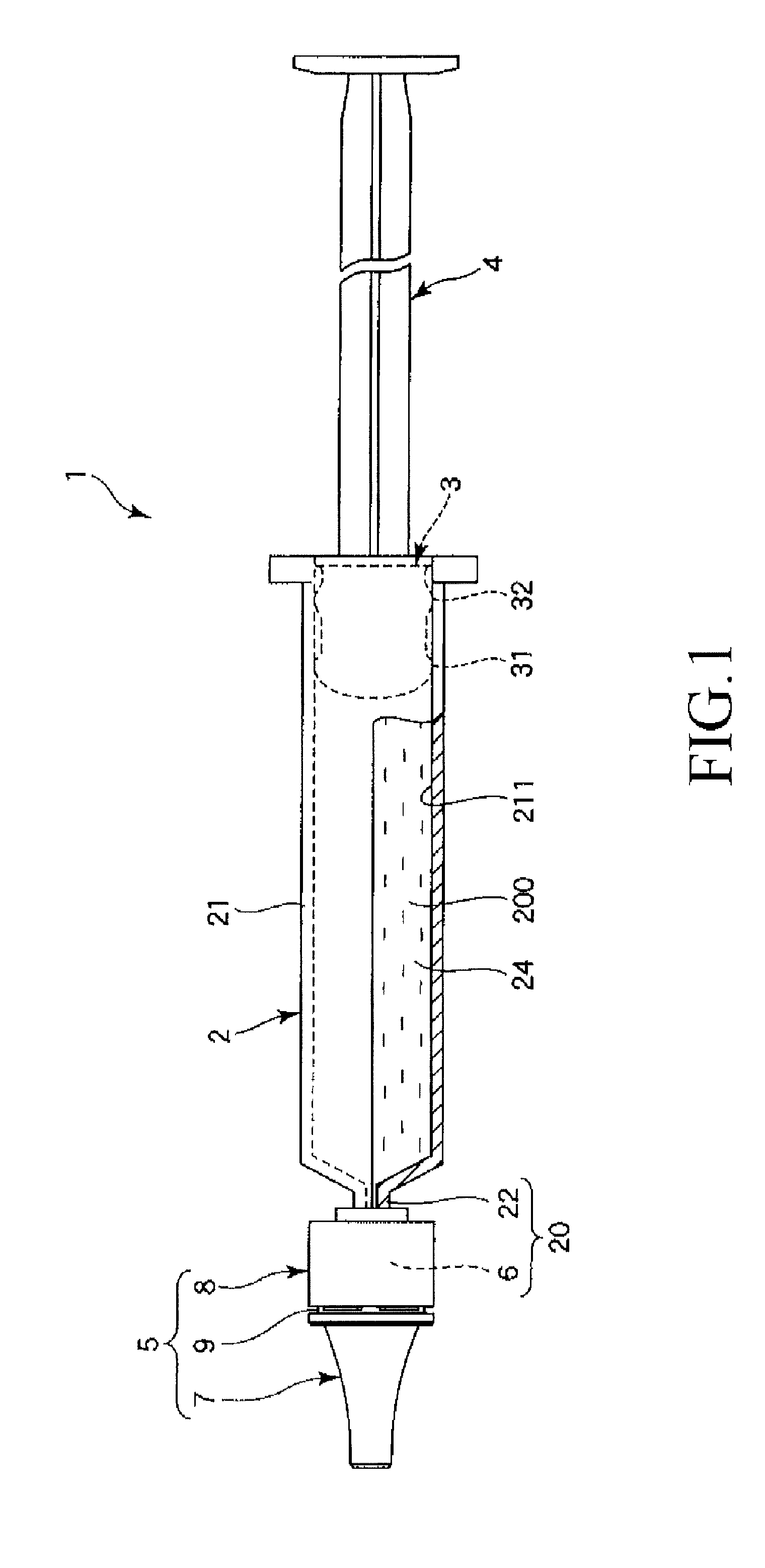
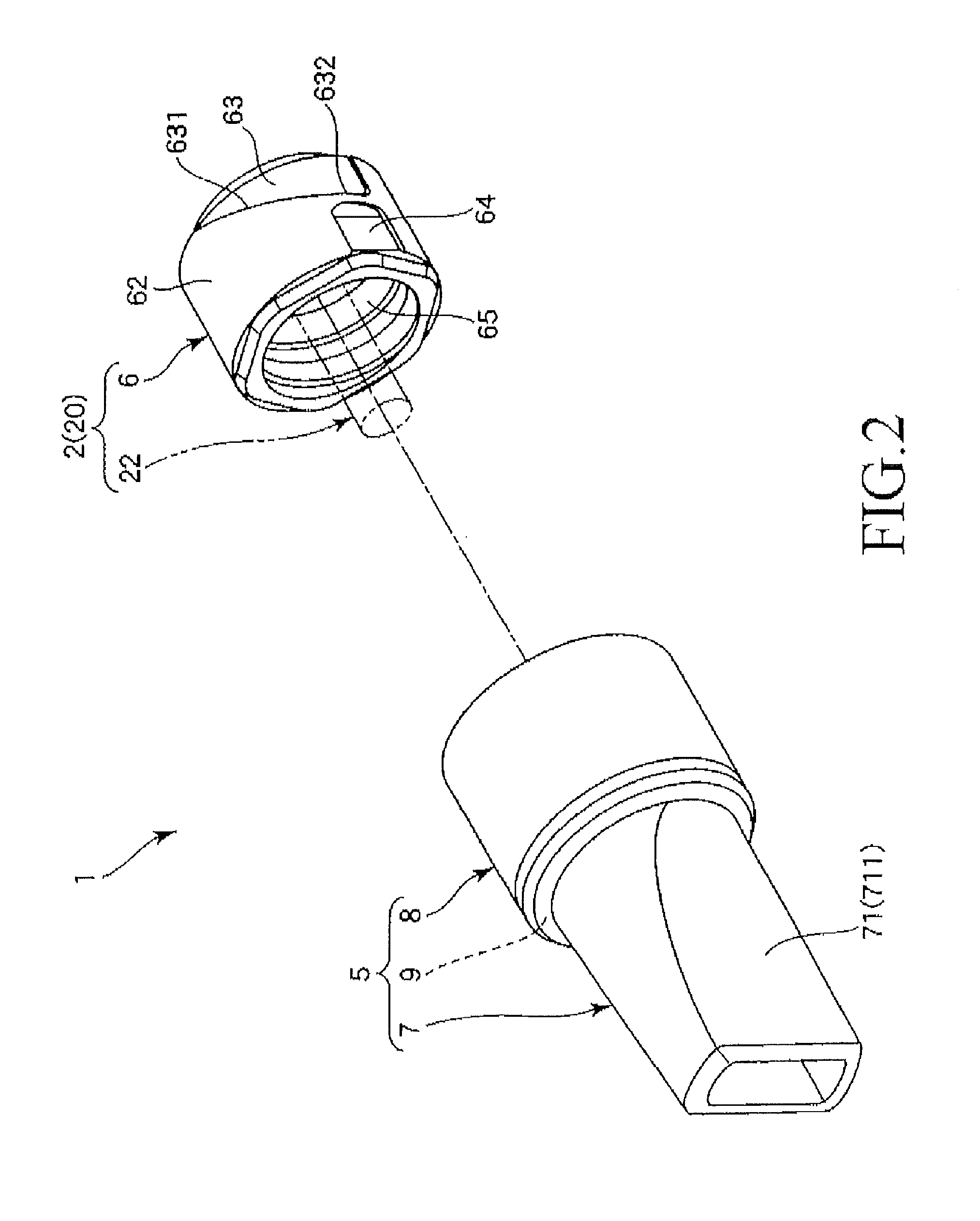
[0028]FIG. 1 is a side view showing an embodiment of the syringe according to the present invention; FIG. 2 is an exploded perspective view of a distal-end side part of the syringe shown in FIG. 1; FIGS. 3 and 4 are longitudinal sectional views for sequentially showing the process of an unsealing operation of the syringe shown in FIG. 1; FIG. 5 is a view showing the positional relationship between a lock adapter of a syringe outer tube and a mounting section of a cap, as viewed from the direction of arrow A in FIG. 3; and FIG. 6 is a view showing the positional relationship between the lock adapter of the syringe outer tube and the mounting section of the cap, as viewed from the direction of arrow B in FIG. 4. Incidentally, in the following, for convenience of description, the right side in FIG. 1 and FIGS. 3 to 6 will be refer...


PUM


Abstract

A syringe includes a syringe outer tube having a spout and a spout-mounted cap. The cap has a cap main body sealing the spout in a liquid-tight manner, a mounting section mounted onto the spout, and a breakable breaking section linking the cap main body and the mounting section to release the link upon breaking. The inner circumferential portion of the mounting section includes protrusions inserted into a groove on the outer circumferential portion of the spout which also has a tilted section tilted relative to the axis of the spout outer circumferential portion. When the cap is rotated along the axial direction of the syringe outer tube, the protrusions move along the tilted section of the groove. The mounting section is thus displaced in the base end direction and the braking section is pulled in the direction and breaks to separate the cap main body from the mounting section.

Description

TECHNICAL FIELD[0001]The present invention relates to a syringe.BACKGROUND ART[0002]There has been known a prefilled syringe in which a sterilized syringe outer tube is filled with a liquid product in an aseptic manner (see, for example, Patent Document 1). The prefilled syringe includes: the syringe outer tube having a spout through which the liquid product is ejected and a lock adapter rotatably supported on the spout; and a cap mounted onto the spout of the syringe outer tube and locked by a lock member. When the prefilled syringe described in Patent Document 1 is, in its unused state or in its unopened sealed state, the cap and the lock adapter are collectively covered with a film with a perforation in a state in which the cap is mounted on the syringe outer tube.[0003]When the prefilled syringe in the unused state is unsealed and the cap is detached but the cap is then remounted, i.e., the prefilled syringe is recapped, without using the prefilled syringe, it is impossible to r...

Claims


Application Information

Patent Timeline
Patent Type & Authority Patents(United States)
IPC IPC(8): B67B1/00B65D47/10A61M5/00
CPCA61M5/5086A61M2005/3104A61M5/28A61M5/347A61M2005/312
Inventor KOYAMA, SHINGO
Owner TERUMO KK
Learn More