Syringe

a technology of syringe and spout, which is applied in the field of syringe, can solve the problems of inability to recapture the spout, the main body configuration of the cap main body is incapable of mounting the spout again, and the broken section is undesired, so as to prevent or suppress, prevent or suppress, and facilitate confirmation

Active Publication Date: 2018-01-09
TERUMO KK
View PDF14 Cites 3 Cited by
  • Summary
  • Abstract
  • Description
  • Claims
  • Application Information

AI Technical Summary

Benefits of technology

[0008]It is an object of embodiments of the present invention to provide a syringe which is excellent in tamperproofness and capable of preventing a breaking section from undesirable breakage.
[0019]According to an embodiment of the present invention, in the mounted state in which the cap main body is mounted on the syringe outer tube, the inner ring is positioned between the reduced diameter section and the lock adapter in the loosely-fitted state and also the outer ring positioned outside the lock adapter in the loosely-fitted state. Further, even when the breaking section is broken to separate the cap main body from the mounting section and an attempt is made to mount the cap main body again on the syringe outer tube, the cap main body cannot be mounted again because of this loosely-fitted state. Consequently, the reduced diameter section of the syringe outer tube is surely prevented from being sealed again with the cap main body, which makes it possible to easily confirm that the syringe has already been unsealed. Thus, the syringe is excellent in tamperproofness, and the unsealed syringe is surely prevented from being used by mistake.
[0020]Additionally, for example, when an external force is applied to the cap main body at the time of transporting the syringe or the like, the cap main body is tilted relative to the axis of the syringe outer tube and stress that may exceeds the breaking limit of the breaking section breakage is likely to be generated at the breaking section. However, the inner ring and outer ring of the cap main body contact the reduced diameter section and the lock adapter, thereby achieving to prevent or suppress the above mentioned stress from being generated. This prevents the breaking section from undesirable breakage.

Problems solved by technology

Further, the cap main body that has been once separated from the mounting section cannot be mounted again on the spout, in other words, the cap main body is configured incapable of recapping the spout.
In this case, there is a problem in that the breaking section is undesirably broken.

Method used


Image

  • Syringe
  • Syringe
  • Syringe

Examples


first embodiment

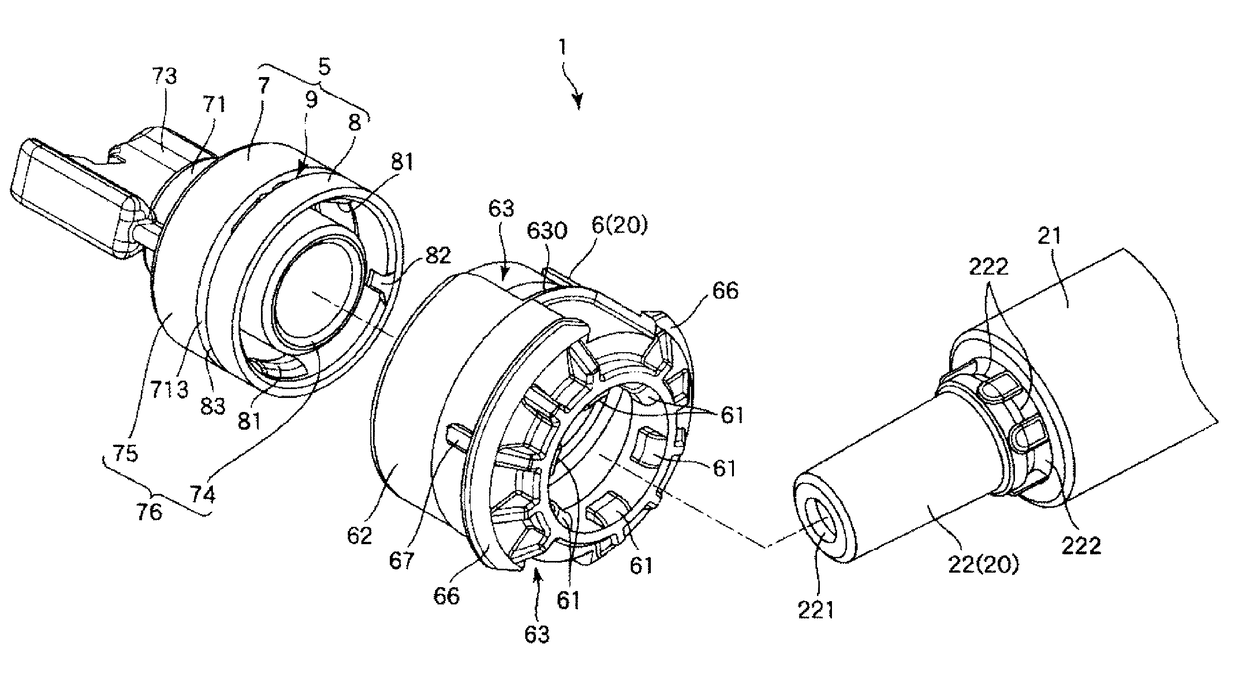
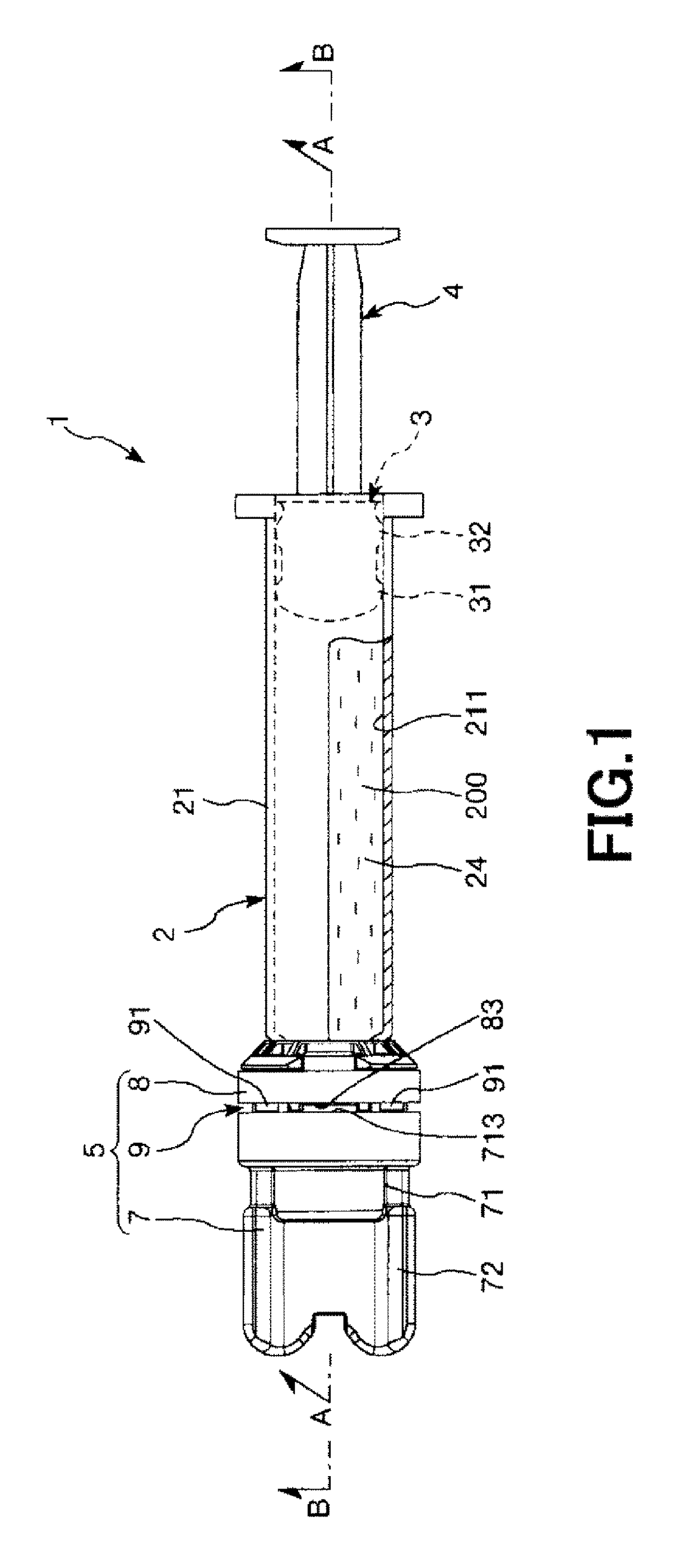
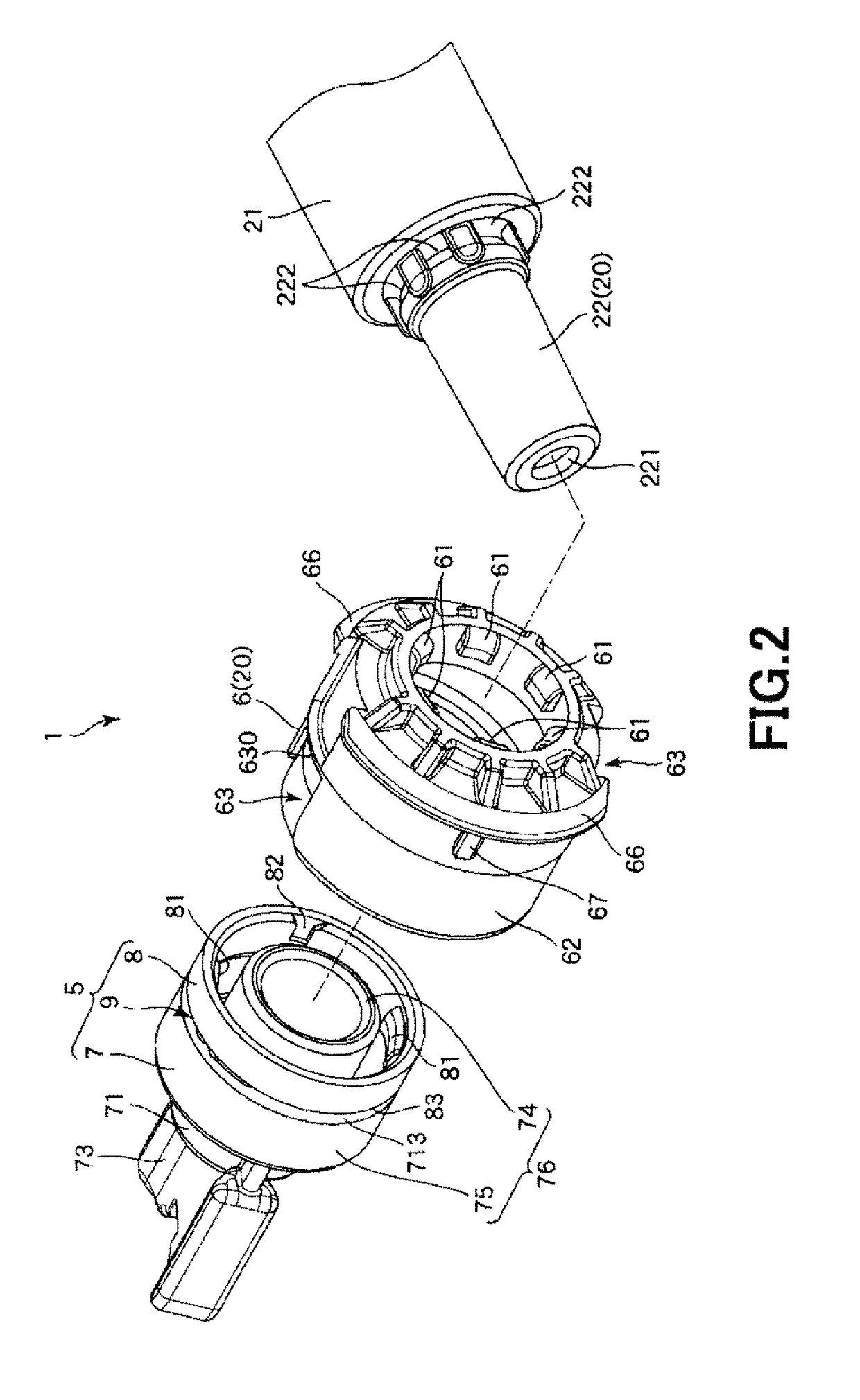
[0030]FIG. 1 is a partial longitudinal cross-sectional side view illustrating a syringe according to a first embodiment of the present invention; FIG. 2 is an exploded perspective view of a portion on a distal end side of the syringe illustrated in FIG. 1; FIG. 3 is a cross-sectional view taken along a line A-A in FIG. 1; FIG. 4 is a cross-sectional view taken along a line B-B in FIG. 1; FIG. 5 is a side view illustrating a state in which the syringe illustrated in FIG. 1 is unsealed; FIG. 6 is a cross-sectional view taken along a line C-C in FIG. 5. Incidentally, in the following, the right side in FIGS. 1 to 6 (same in FIGS. 7 and 8) will be referred to as a “proximal end,” and the left side as a “distal end” for convenience of description. Further, in FIGS. 3, 4 and 6, a filled liquid product is omitted.

[0031]A syringe 1 illustrated in FIG. 1 is a prefilled syringe, which includes a syringe outer tube (hereafter referred to simply as “outer tube”) 2, a gasket 3 disposed inside th...

second embodiment

[0078]FIGS. 7 and 8 are views illustrating positional relationships between a lock adapter of a syringe outer tube and a mounting section of a cap in a process of unsealing operation at a syringe according to an embodiment of the present invention (second embodiment).

[0079]Now, the second embodiment of the syringe according to the present invention will be described below with reference to the drawings. However, description will be given focusing on differences from the above-described embodiment, and description for the same matters same will be omitted.

[0080]The present embodiment is the same as the first embodiment except for having a different configuration in the lock adapter.

[0081]As illustrated in FIGS. 7 and 8, according to the present embodiment, each of grooves 63 is formed on a more proximal end side than a crest portion 630 of an outer circumferential portion 62 of the lock adapter 6. In a mounted state, each of projections 81 of a mounting section 8 of a cap 5 is insert...


PUM


Abstract

A syringe includes a syringe outer tube including a tubular-shaped outer tube main body configured to be filled with a liquid, a reduced diameter section located at a distal end of the outer tube main body in a projecting manner, and configured to allow the liquid to pass therethrough, the reduced diameter section having an outside diameter that is smaller than a diameter of the outer tube main body, and a ring-shaped lock adapter concentrically disposed at an outer circumferential portion of the reduced diameter section and configured to fix a mating member connected to the reduced diameter section; and a cap including a cap main body mounted on the syringe outer tube and configured to seal the reduced diameter section in a liquid-tight manner when the cap main body is in a mounted state, a ring-shaped mounting section disposed at a proximal end side of the cap main body and mounted on an outer circumferential portion of the lock adapter, and a breaking section that forms a link between the cap main body and the mounting section and that is configured to release the link by breakage.

Description

CROSS-REFERENCE TO RELATED APPLICATIONS[0001]This application is a continuation application filed under 35 U.S.C. 111(a) claiming the benefit under 35 U.S.C. §§120 and 365(c) of PCT International Application No. PCT / JP2013 / 057192 filed on Mar. 14, 2013, which is based upon and claims the benefit of priority of Japanese Application No. 2012-073040 filed on Mar. 28, 2012, the entire contents of which are hereby incorporated by reference in their entireties.BACKGROUND[0002]Technical Field[0003]The present disclosure relates to a syringe.[0004]Background Art[0005]A prefilled syringe in which a sterilized syringe outer tube is filled with a liquid product in an aseptic manner is known (see, for example, WO 2011 / 108574 A). The prefilled syringe disclosed in WO 2011 / 108574 A includes: the syringe outer tube having a spout through which the liquid product is ejected, and a lock adapter rotatably supported at the spout; and a cap mounted on the spout of the syringe outer tube. Also, the cap ...

Claims


Application Information

Patent Timeline
Patent Type & Authority Patents(United States)
IPC IPC(8): A61M5/00A61M5/50A61M5/34A61M5/31
CPCA61M5/5086A61M5/344A61M2005/3118A61M2005/312A61M2005/3104A61M5/347A61M2005/3103
Inventor OKIHARA, HITOSHIKOYAMA, SHINGO
Owner TERUMO KK
Why Eureka
Try Eureka