Lateral entry insert for cup trial

a cup and insert technology, applied in the field of shoulder trials, can solve problems such as problems such as achieving appropriate tensioning during rsa, and achieve the effect of increasing joint tension and reducing and dislocating joints

Active Publication Date: 2014-03-04
HOWMEDICA OSTEONICS CORP
View PDF237 Cites 24 Cited by
  • Summary
  • Abstract
  • Description
  • Claims
  • Application Information

AI Technical Summary

Benefits of technology

[0008]The lateral engagement and disengagement of the insert trial and insert cup allows any size insert trial and cup to be used during the trialing process in contrast to having to reduce and distract the trials from each other prior to and after use.
[0009]In the past, there have been issues with achieving appropriate tensioning during RSA due to difficulties in inserting and removing the trials from between the humeral components and the glenosphere component on the glenoid. The trial assembly of the present invention provides a way of reducing and dislocating the joint without any temporary increase in joint tension that is usually experienced when reducing the ball up, over, and into the insert trial socket.
[0013]In yet another embodiment of this first aspect, the recess of the trial insert begins at the outer circumference of the shaft portion and terminates adjacent a central axis of the trial insert. When a longitudinal axis of the centering member is collinear with the central axis of the trial insert, the trial insert may be rotated in a radial direction about the central axis thereof. Further, rotating the trial insert 90° in either a first or second radial direction about a central axis thereof results in lateral locking of the trial insert and trial cup such that the trial insert and trial cup cannot be uncoupled by offsetting the longitudinal axis of the centering member of the trial cup and central axis of the trial insert. Further still, rotating the trial insert another 90° in either a first or second radial direction about the central axis thereof results in lateral unlocking of the trial insert and trial cup such that the trial insert and trial cup can be uncoupled by offsetting the longitudinal axis of the centering member of the trial cup and central axis of the trial insert.
[0020]In one embodiment of this second aspect, when the central longitudinal axes of the centering member and trial insert are collinear, the trial insert may be rotated in a radial direction about the central longitudinal axis of the centering member. Further, rotating the trial insert 90° in either a first or second radial direction about a central axis thereof results in lateral locking of the trial insert and trial cup such that the trial insert and trial cup cannot be uncoupled by offsetting the longitudinal axis of the centering member of the trial cup and central axis of the trial insert. Further still, rotating the trial insert another 90° in either a first or second radial direction about the central axis thereof results in lateral unlocking of the trial insert and trial cup such that the trial insert and trial cup can be uncoupled by offsetting the longitudinal axis of the centering member of the trial cup and central axis of the trial insert.

Problems solved by technology

In the past, there have been issues with achieving appropriate tensioning during RSA due to difficulties in inserting and removing the trials from between the humeral components and the glenosphere component on the glenoid.

Method used


Image

  • Lateral entry insert for cup trial
  • Lateral entry insert for cup trial
  • Lateral entry insert for cup trial

Examples


Embodiment Construction

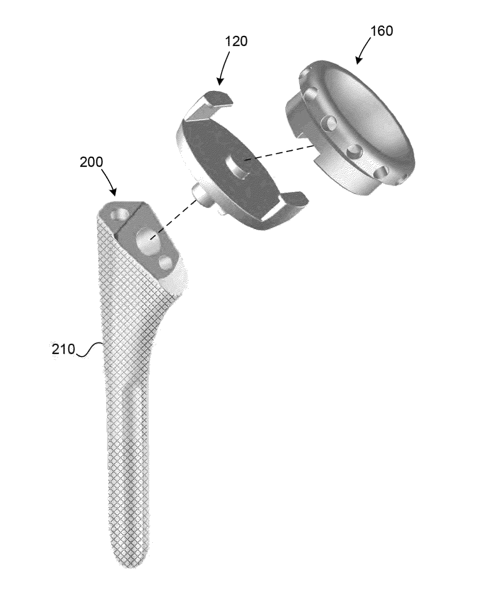
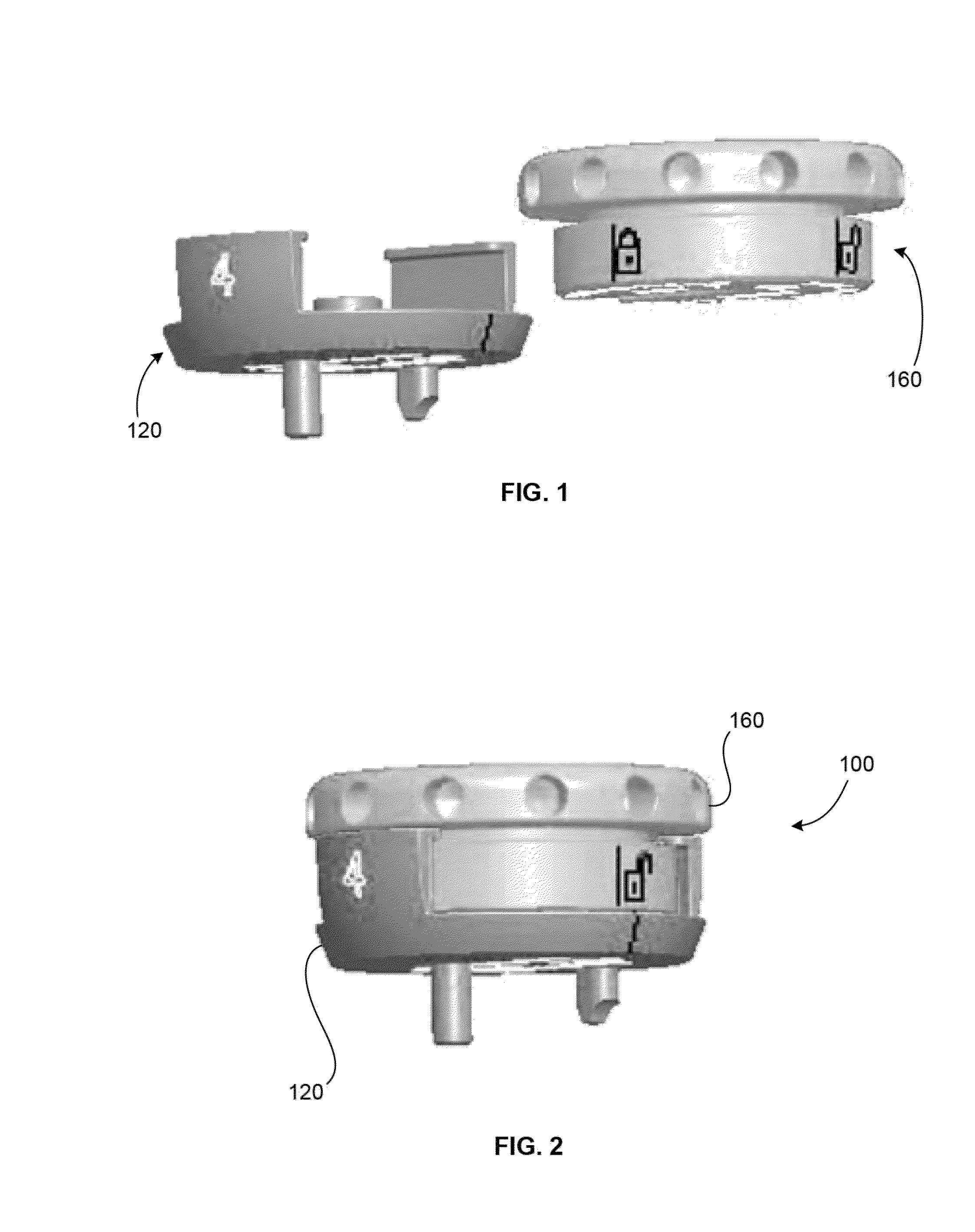
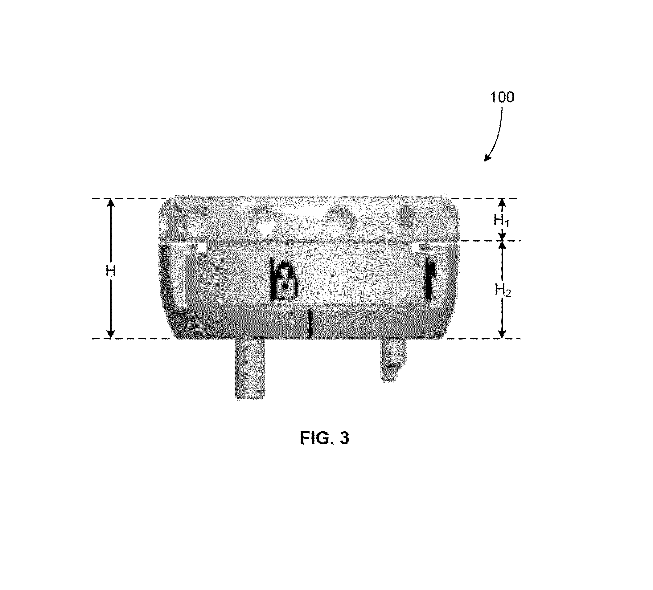
[0042]Referring to FIGS. 1-3, there is shown an embodiment of a trial assembly of the present invention designated generally by reference numeral 100. As shown in those figures, trial assembly 100 includes a trial cup 120 and a trial insert 160.

[0043]FIGS. 4A-D show an embodiment of trial cup 120. As shown in these figures, trial cup 120 includes a distal end surface 122 and a proximal end surface 124. Proximal end surface 124 includes first and second flanges 126, 128 and a centering member 130 protruding outwardly therefrom. Proximal end surface 124 preferably includes a marker 144 thereon as shown in FIG. 4D.

[0044]First and second flanges 126, 128 preferably extend outwardly from at least a portion of an outer circumference 136 of proximal end surface 124 of trial cup 120. First and second flanges 126, 128 include an engagement member 132, 134 respectively. Engagement members 132, 134 preferably extend outwardly from inner surfaces of first and second flanges 126, 128. Engagement...


PUM


Abstract

Trials for a reverse shoulder system are described. The trials generally include an insert housed within a humeral cup. The insert has a proximal end and a distal end, the proximal end having a concave recess therein adapted to receive a glenosphere prosthesis. The distal end of the insert includes a shaft, the shaft is substantially housed within the confines of the humeral cup. A distal end of the humeral cup is inserted in a humeral stem.

Description

FIELD OF THE INVENTION[0001]The present invention relates to a shoulder trial for reverse shoulder arthroplasty (RSA), and in particular it relates to such a trial including an insert and humeral cup that are configured to engage one another by sliding the insert from a transverse or lateral direction into engagement with the humeral cup.BACKGROUND OF THE INVENTION[0002]The successful outcome of RSA depends greatly on proper soft tissue tension in the shoulder joint. The stability of the shoulder joint is generally maintained from significant deltoid tension holding this ball and socket joint together. Some RSA systems require the surgeon to use a trial and error approach in establishing proper soft tissue tension. Such approaches often take several attempts before adequate stability is achieved.[0003]When performing a trialing step in a reverse shoulder procedure, one important aspect is to determine the correct height of the humeral insert implant that will ultimately be chosen fo...

Claims


Application Information

Patent Timeline
Patent Type & Authority Patents(United States)
IPC IPC(8): A61F2/40
CPCA61F2002/4022A61F2002/30616A61F2/4003A61F2/4684A61F2002/30383A61F2/4014A61F2002/30476A61F2/4637
Inventor VISCARDI, DAVIDRAO, KOUSTUBH
Owner HOWMEDICA OSTEONICS CORP
Why Eureka
Try Eureka