Back focused anti-scatter grid

a grid and anti-scatter technology, applied in the direction of electrostatic spraying apparatus, spraying apparatus, diaphragm/collimeter handling, etc., can solve the problems of substrate degradation, grid difficulty, grid irregularity,

Active Publication Date: 2014-03-04
GENERAL ELECTRIC CO
View PDF9 Cites 23 Cited by
  • Summary
  • Abstract
  • Description
  • Claims
  • Application Information

AI Technical Summary

Problems solved by technology

One problem with the grids as described above is that the regularity thereof is not sufficient, particularly in applications where the grid is fixed in relation to the image receptor.
Furthermore, these grids are difficult to produce.
One problem is that, in use, it has been observed that the substrate produced diffuse radiation SG which was not stopped by the strips obtained by filling the groove such that the primary radiation Sp passing through the substrate is degraded by the radiation SG scattered by the substrate.
In use, the performances of such a grid are limited.

Method used


Image

  • Back focused anti-scatter grid
  • Back focused anti-scatter grid
  • Back focused anti-scatter grid

Examples


Embodiment Construction

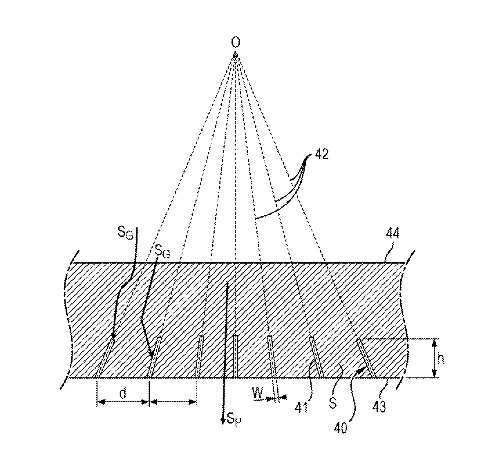
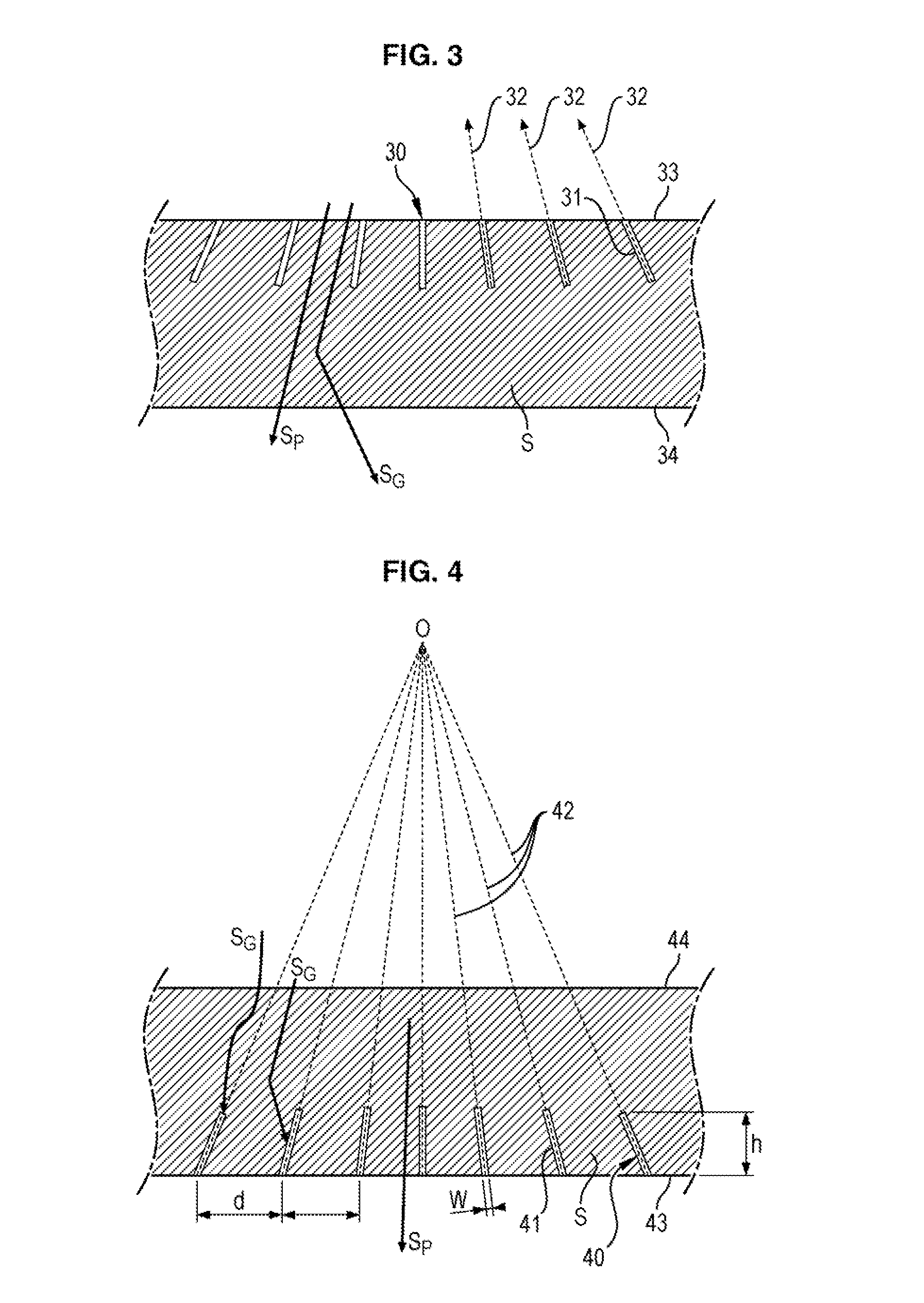
[0033]FIG. 4 illustrates a cross-section view of a focussed anti-scatter grid.

[0034]Such a grid comprises a substrate S having a first face 44 and a second face 43.

[0035]The substrate S comprises a plurality of grooves 40 opening onto the first face 44 of the substrate S and not opening onto the second face 43.

[0036]The substrate S has low X-ray absorption properties and the grooves 40 are filled with an absorbent material 41 having X-ray absorption properties.

[0037]The grooves 40 each have an orientation. The orientation is such that the planes 42 of all grooves 40 are convergent and intersect along a line D situated on the side of the second face 44 where the grooves 40 do not open.

[0038]Such a grid is produced according to the process described in the document U.S. Pat. No. 7,356,126.

[0039]The main steps of this process consist of forming in a substrate, having low X-ray absorption properties, a plurality of grooves. The grooves are for example formed by means of a cutting tool, ...


PUM


Abstract

An anti-scatter grid for an x-ray imaging system. The grid has substrate having a first face and a second face. The substrate has a plurality of grooves opening onto the first face of the substrate and not opening onto the second face. The substrate has high X-ray absorption properties. Each groove has an orientation such that the planes of all the grooves are convergent and intersect along a line situated on the side of the second face where the grooves do not open.

Description

BACKGROUND OF THE INVENTION[0001]1. Field of the Invention[0002]The field of the invention relates to anti-scatter grids used in medical imaging by means of radiation.[0003]2. Description of the Prior Art[0004]Anti-scatter grids are widely used in medical imaging to improve image contrast quality.[0005]FIG. 1 illustrates a conventional medical imaging system.[0006]Such a system comprises a radiation source 1, for example of the X-ray type, which projects a conical beam for illuminating an object 2, such as for example a part or an organ of a patient to be examined before reaching an image receptor 3 comprising a detector array.[0007]An anti-scatter grid 4 is inserted between the source 1 and the image receptor 3 so as to attenuate the radiation not coming directly from the source 1, particularly scattered radiation.[0008]Conventionally, an anti-scatter grid comprises an alternation of thin plane strips consisting of a highly X-ray absorbent material, such as lead for example, separa...

Claims


Application Information

Patent Timeline
Patent Type & Authority Patents(United States)
IPC IPC(8): G21K1/00
CPCG21K1/025
Inventor KLAUSZ, REMY, ANDRE
Owner GENERAL ELECTRIC CO
Why Eureka
Try Eureka