Pressure management system for well casing annuli

a management system and well casing technology, applied in the direction of survey, wellbore/well accessories, construction, etc., can solve the problems of pressure changes inside the pressure containment, and achieve the effect of enhancing risk management and safety, and better control and understanding

Active Publication Date: 2014-04-01
HALLIBURTON CO
View PDF20 Cites 50 Cited by
  • Summary
  • Abstract
  • Description
  • Claims
  • Application Information

AI Technical Summary

Benefits of technology

[0010]The invention leads to better control and understanding of any pressure / temperature excursions inside a well casing annulus as the method and apparatus proposed enable distinguishing whether a change in containment pressure and temperature is caused by process or environmental fluctuations, or by a hazardous pressure leak from the well. Thus, the invention enhances the risk management and safety of the well as well as the surrounding environments, permitting any required action to be taken earlier to avoid hazardous events. This can last over the lifetime of the well.
[0013]A second aspect of the invention is that the pressure management system is able to predict the future pressure / temperature profile of the annuli space as a function of load changes. Typically load changes are caused by fluctuations in the process or the environment, which in turn induce pressure changes inside the pressure containment system of a well. Such changes are not hazardous in their origin and the ability to address them will contribute to the safety assessment of the well. As a result, the real-time acquisition of process and environment data in combination with the in-situ measurements constitute an important advance over the prior art in that the present invention can help management to anticipate and react to potential problems before they occur. In addition, the remote sensor package can be dressed with numerous and different evaluation sensors that may be important to evaluate the status and integrity of a plurality of well pressure containment systems.
[0015]Another aspect of the present invention is a Sensor Energizer Unit (“SEU”) that is typically part of or attached to the well completion tubing. The SEU is adapted to host the Wireless Sensor Unit. The SEU consists of three main elements. The first and main element of the SEU is an Electromagnetic Armature (“EA”), the second element of the SEU is an Adjustable Mandrel (“AM”), and the third element of the SEU is a Cable Adaptor (“CA”). The EA provides as a combination of both a power source and a communications link for the WSU. The principal transmission of the EA is by low frequency induction or electromagnetic (“EM”) means, which is picked up and converted to electrical energy by the WSU. To ensure optimum efficiency vis-à-vis the WSU, the EA is attached to the AM, which enhances the facility to “fine tune” or optimize the efficiency to host the WSU by vertical adjustment means. Also attached to the EA is a Cable Adaptor (“CA”) that connects the control cable from outside of the well. The control cable is attached to the completion tubing by traditional cable clamps and exits the well through the wellhead, all according to prior art means. Typically, the control cable is a single-conductor Tubing Electric Cable (“TEC”) type, providing power to the SEU as well as communication between the mentioned components and the monitoring facilities (i.e., outside the well).
[0017]Depending on the degree of risk assessment required, the SEU may also include a Sensor Package (“SP”) equal to that of the WSU to enhance more complex evaluation of the integrity of its pressure containment system.

Problems solved by technology

Typically load changes are caused by fluctuations in the process or the environment, which in turn induce pressure changes inside the pressure containment system of a well.

Method used


Image

  • Pressure management system for well casing annuli
  • Pressure management system for well casing annuli
  • Pressure management system for well casing annuli

Examples


Embodiment Construction

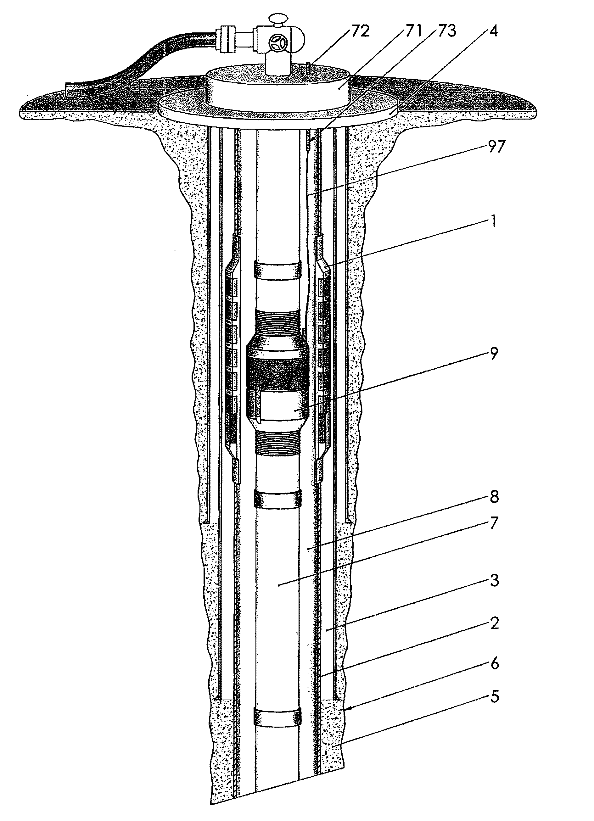
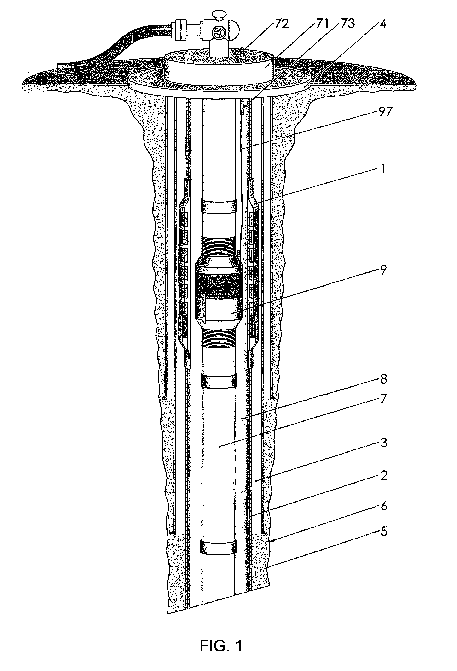
[0035]This invention relates to a system for monitoring the pressure integrity of well casing annuli. The annulus to monitor is typically the barrier that is closest to the well production system in order to avoid leaks and enhance safe operation. In particular as shown in FIG. 1, a Wireless Sensor Unit (“WSU”) 1 in the present invention is made part of the casing program of the main production barrier 2 of the well. Referring to FIG. 2, a casing section 20 of the WSU 1 is made of a non-magnetic material and hosts a Sensor Package 10 and a plurality of Electromagnetic Transceivers (11a-f). For the purpose of this invention, the Sensor Package 10 is configured to measure and monitor the annular space 3 outside the main production barrier 2 of the well producing system (shown in FIG. 1).

[0036]Referring again to FIG. 1, this annular space 3 is also often referred to as Annulus-B, and the WSU 1 is typically positioned close to and underneath the wellhead structure or housing 4. The well...


PUM


Abstract

An apparatus and method to provide monitoring of pressure outside the wellbore casing of a well in which a Wireless Sensor Unit is placed externally of a section of non-magnetic casing. An internal Sensor Energizer Unit is placed inside the wellbore casing. The Wireless Sensor Unit includes one or more sensors to measure the pressure and / or temperature of the surroundings. The Wireless Sensor Unit and the Sensor Energizer Unit communicate using electromagnetic modulation techniques, and the Wireless Sensor Unit may be powered by means of power harvesting from the Sensor Energizer Unit.

Description

BACKGROUND OF THE INVENTIONField of the Invention[0001]This invention relates generally to a method and apparatus for the management of the pressure containing integrity of oil and gas production, injection and observation wells, and more particularly to a method and apparatus to accurately monitor in-situ the pressure and / or temperature in one or more well casing annuli without compromising the integrity of the well or well design in any way.[0002]The management of the pressure containing integrity of oil and gas wells constitutes an ongoing concern of the petroleum industry. Those concerns are mainly due to the enormous monetary expenses involved in manufacturing and running any type of petroleum well as well as the risks associated with its environmental and safety issues. Herein, a petroleum type well is defined as any type of well that is drilled and equipped for the purpose of producing or storage of hydrocarbon fractures from or to subsurface formations. Further, petroleum ty...

Claims


Application Information

Patent Timeline
Patent Type & Authority Patents(United States)
IPC IPC(8): E21B47/12E21B47/10E21B47/00E21B47/06E21B47/01
CPCE21B47/0006E21B47/065E21B47/10E21B47/122E21B47/01E21B41/0085E21B47/06E21B47/00E21B47/007E21B47/07E21B47/13H04B5/00
Inventor GODAGER, OIVIND
Owner HALLIBURTON CO
Why Eureka
Try Eureka