Patient monitoring system with health status indicator

a monitoring system and health status technology, applied in the field of patient monitoring systems with health status indicators, can solve the problems of difficult to efficiently evaluate all the displayed information and identify the specific patients requiring attention

Active Publication Date: 2014-04-15
GENERAL ELECTRIC CO
View PDF29 Cites 10 Cited by
  • Summary
  • Abstract
  • Description
  • Claims
  • Application Information

AI Technical Summary

Problems solved by technology

One problem with such conventional multi-patient displays is that it can be difficult to efficiently evaluate all the displayed information and identify those specific patients requiring attention.

Method used


Image

  • Patient monitoring system with health status indicator
  • Patient monitoring system with health status indicator
  • Patient monitoring system with health status indicator

Examples


Embodiment Construction

[0011]In the following detailed description, reference is made to the accompanying drawings that form a part hereof, and in which is shown by way of illustration specific embodiments that may be practiced. These embodiments are described in sufficient detail to enable those skilled in the art to practice the embodiments, and it is to be understood that other embodiments may be utilized and that logical, mechanical, electrical and other changes may be made without departing from the scope of the embodiments. The following detailed description is, therefore, not to be taken as limiting the scope of the invention.

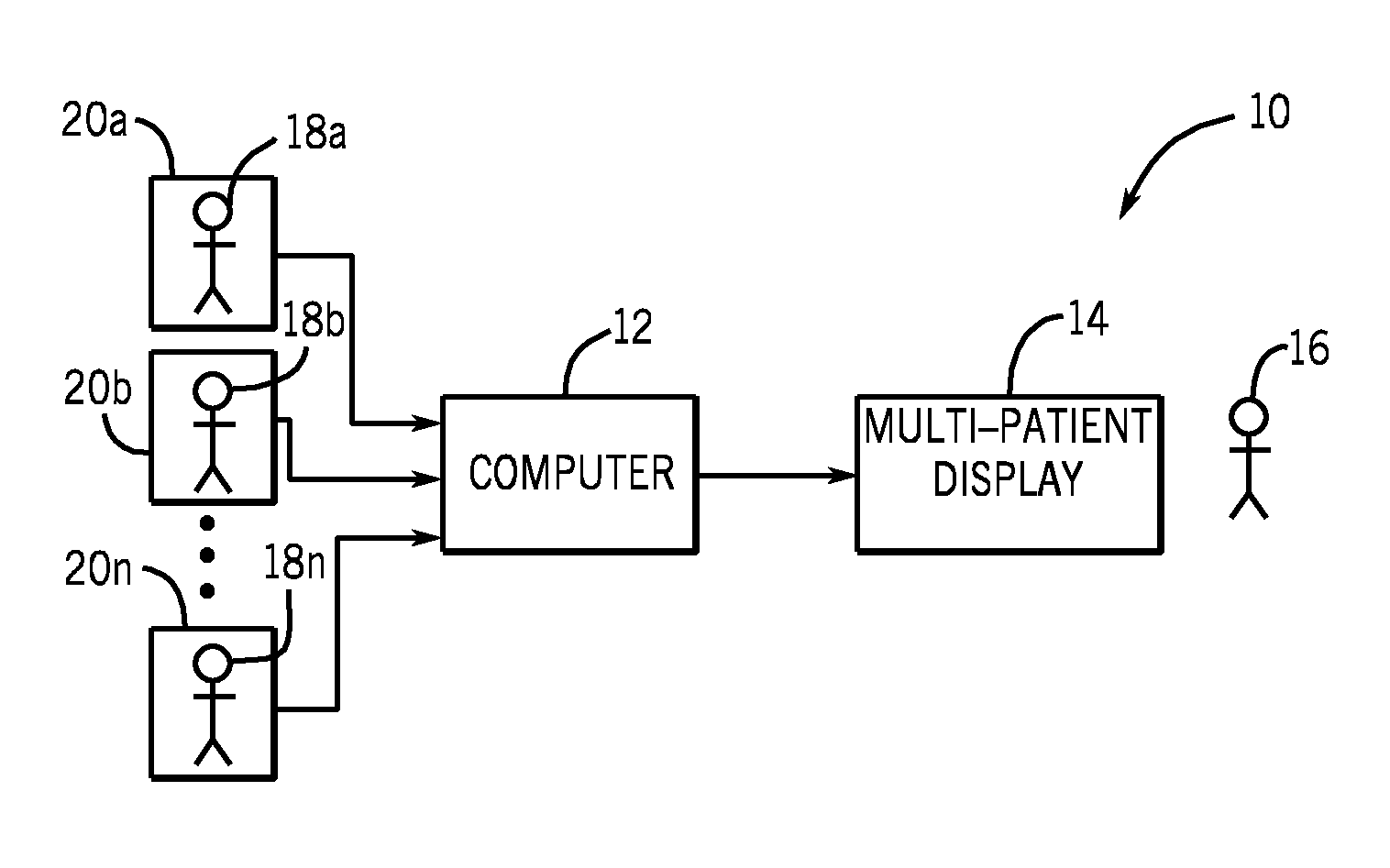
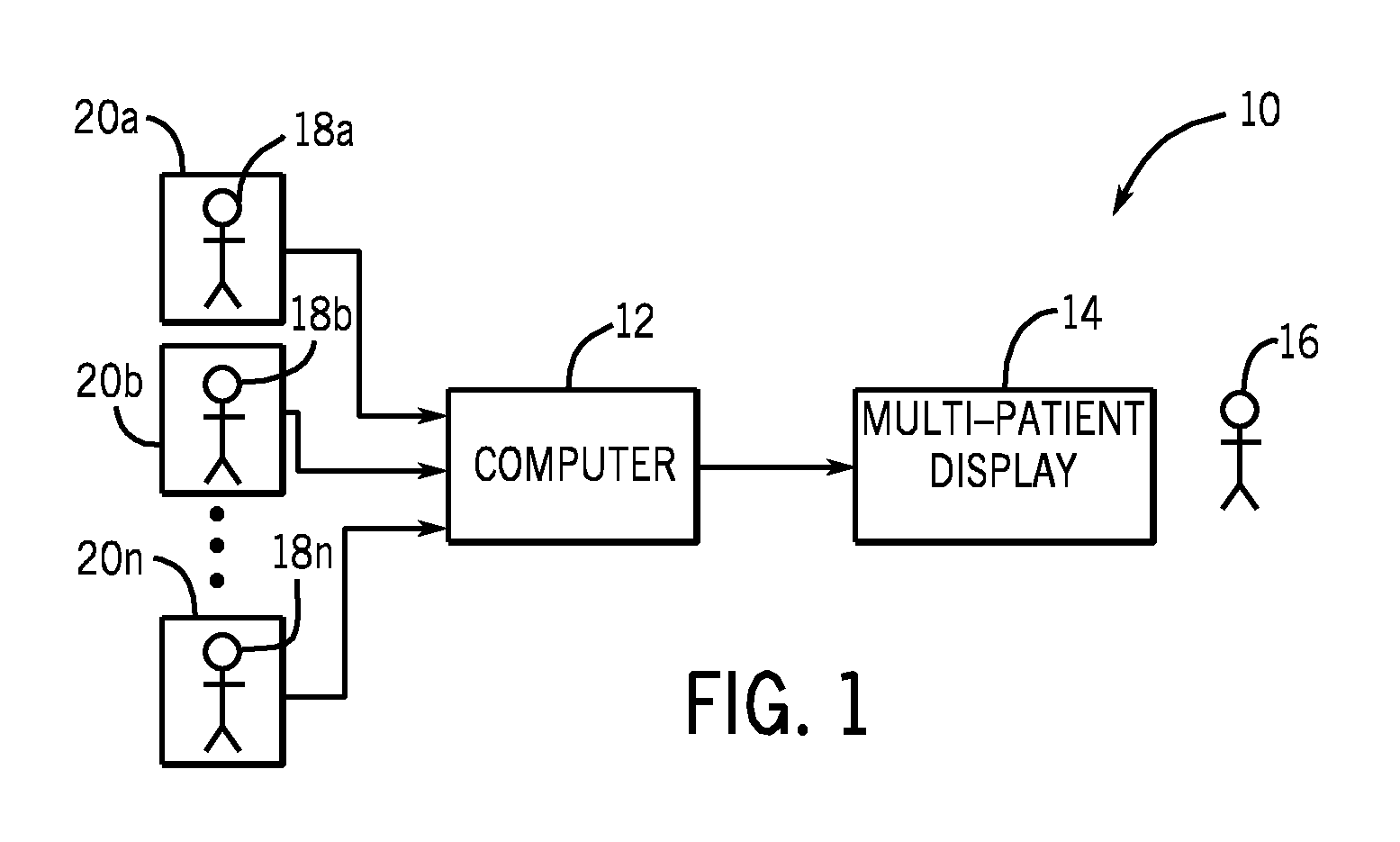
[0012]Referring to FIG. 1, a patient monitoring system 10 is shown in accordance with one embodiment. The patient monitoring system 10 includes a computer 12 and a display 14. The patient monitoring system 10 will hereinafter be described in accordance with an embodiment as a centralized patient monitoring system 10 adapted to enable a single technician 16 to generally simulta...


PUM


Abstract

A patient monitoring system is disclosed herein. The patient monitoring system includes a computer adapted to assess the health of a patient, and to generate a health status indicator for the patient. The health status indicator comprising a visual gradient adapted to visually convey the assessed health of the patient. The system also includes a display operatively connected to the computer. The display is configured to display the health status indicator comprising the visual gradient.

Description

BACKGROUND OF THE INVENTION[0001]The subject matter disclosed herein relates to a patient monitoring system with a health status indicator.[0002]Multi-patient displays enable a single technician to generally simultaneously monitor a plurality of patients. Multi-patient displays are commonly implemented in centralized patient monitoring systems wherein a plurality of technicians collectively monitor a large number of patients from a single location, and in hallway display systems wherein patient data pertaining to a plurality of different patients is visually conveyed in a hospital hallway.[0003]Some conventional multi-patient displays are configured to enable a single technician to monitor as many as 96 patients. One problem with such conventional multi-patient displays is that it can be difficult to efficiently evaluate all the displayed information and identify those specific patients requiring attention.BRIEF DESCRIPTION OF THE INVENTION[0004]The above-mentioned shortcomings, dis...

Claims


Application Information

Patent Timeline
Patent Type & Authority Patents(United States)
IPC IPC(8): A61B5/00G06T11/00G06F19/00G16H40/63G16Z99/00
CPCG06F19/3487G06F19/3431G06F19/30A61B5/0002G06F19/345G06T11/00G06T11/001G06F19/3406Y10S128/92A61B5/4842A61B5/00A61B5/7445G06T2210/41A61G12/00A61B5/74G16H40/63G16H50/30G16H15/00G16H50/20G16Z99/00
Inventor ALBERTE, JR., ROBERT JOSEPHDAVIS, CARL CLAUDESITZMAN, DAVID ALAN
Owner GENERAL ELECTRIC CO
Why Eureka
Try Eureka