
Gambrel device

a gambrel and device technology, applied in the field of hunting aids, can solve the problems of inability to move an animal from an inaccessible location, inconvenient dragging of existing hoisting devices, and inability to meet the needs of transportation, so as to improve the appreciation of the contribution of the art

Inactive Publication Date: 2014-04-29
SCOTT TERRANCE
View PDF21 Cites 11 Cited by
  • Summary
  • Abstract
  • Description
  • Claims
  • Application Information

AI Technical Summary

Benefits of technology

The invention is a new type of gambrel that includes a hoisting construction integrated with it. This allows for the hoisting and suspension of game or objects from an existing support structure, and can also be used to relocate game. The tam also includes an electrically operated hoisting configuration with an electric winch. Additionally, the gambrel has a skid surface that can be dragged across a ground surface to locate an animal for loading into a vehicle or processing. The ruling frame of the gambrel is made of a single plate of material with angled apexes, and a guide eyelet is formed through the top apex. Overall, the invention has improved features and advantages over existing hoisting and dragging devices, making it more versatile and efficient.

Problems solved by technology

Further, relocating an animal from an inaccessible location is another challenge often encountered by a hunter.
While the existing devices fulfill their respective objectives and requirements, these devices have disadvantages.
For example, existing gambrel designs are used for hanging and not well suited to be dragged across a ground surface.
Existing hoisting devices are comprised of bulky and cumbersome constructions.
Further, existing hoisting devices require manual labor in operating a winching device to hoist a gambrel and animal.
Because of this, suspending large animals in the field can be quite difficult.

Method used


Image

  • Gambrel device
  • Gambrel device
  • Gambrel device

Examples


Embodiment Construction

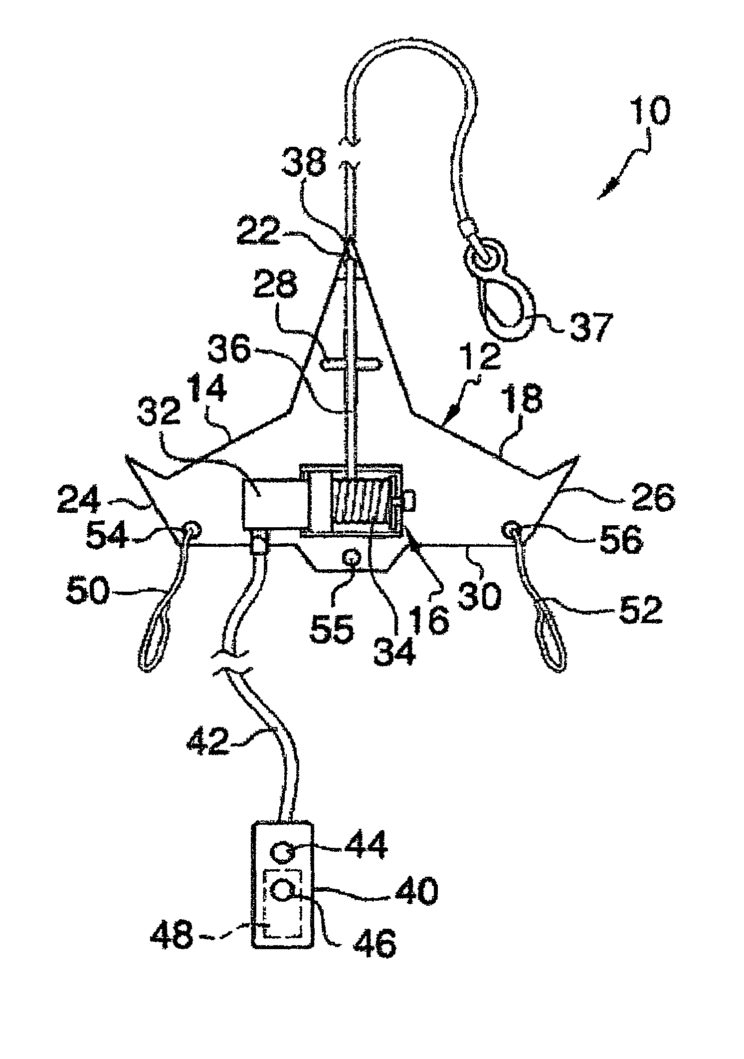
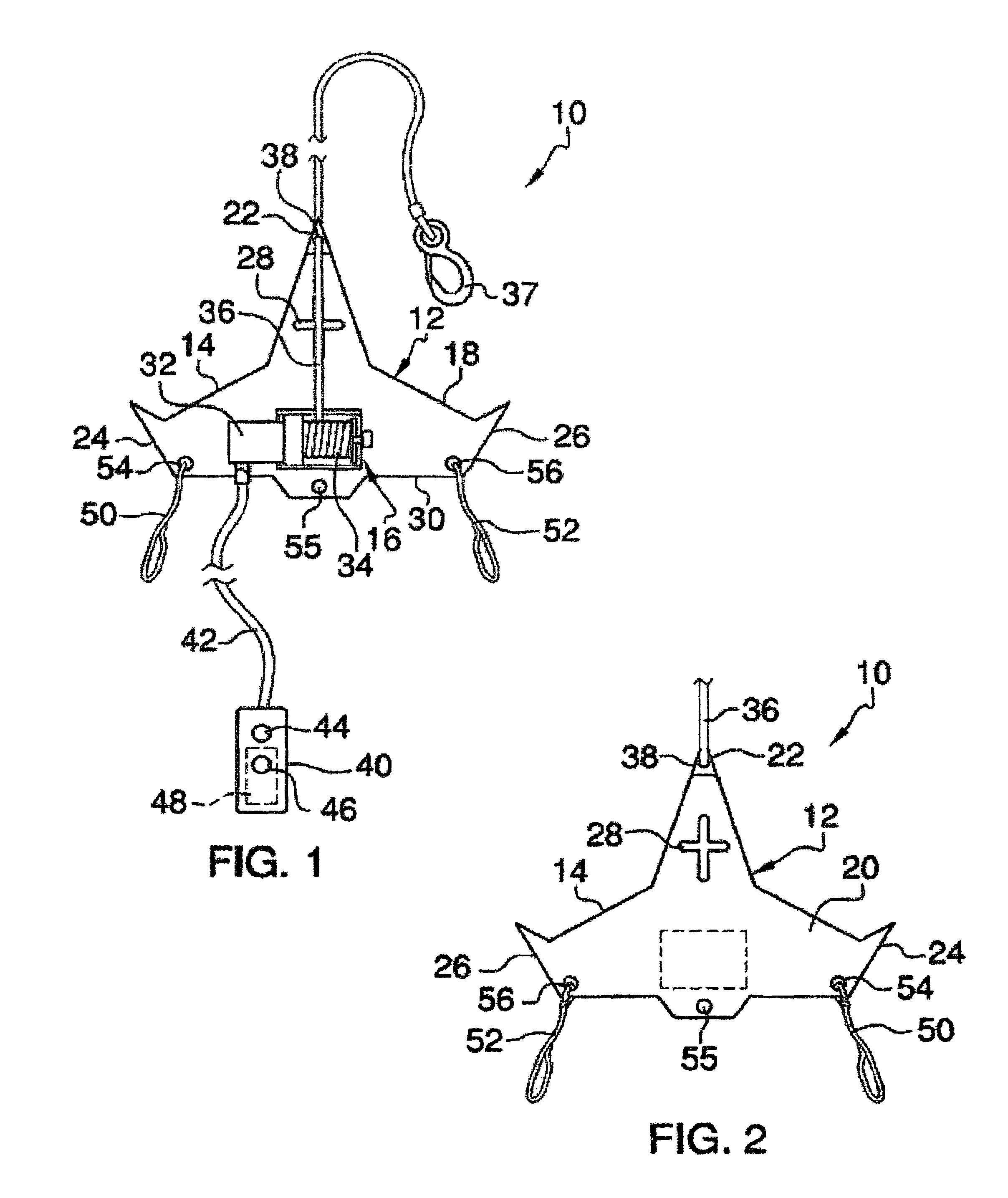
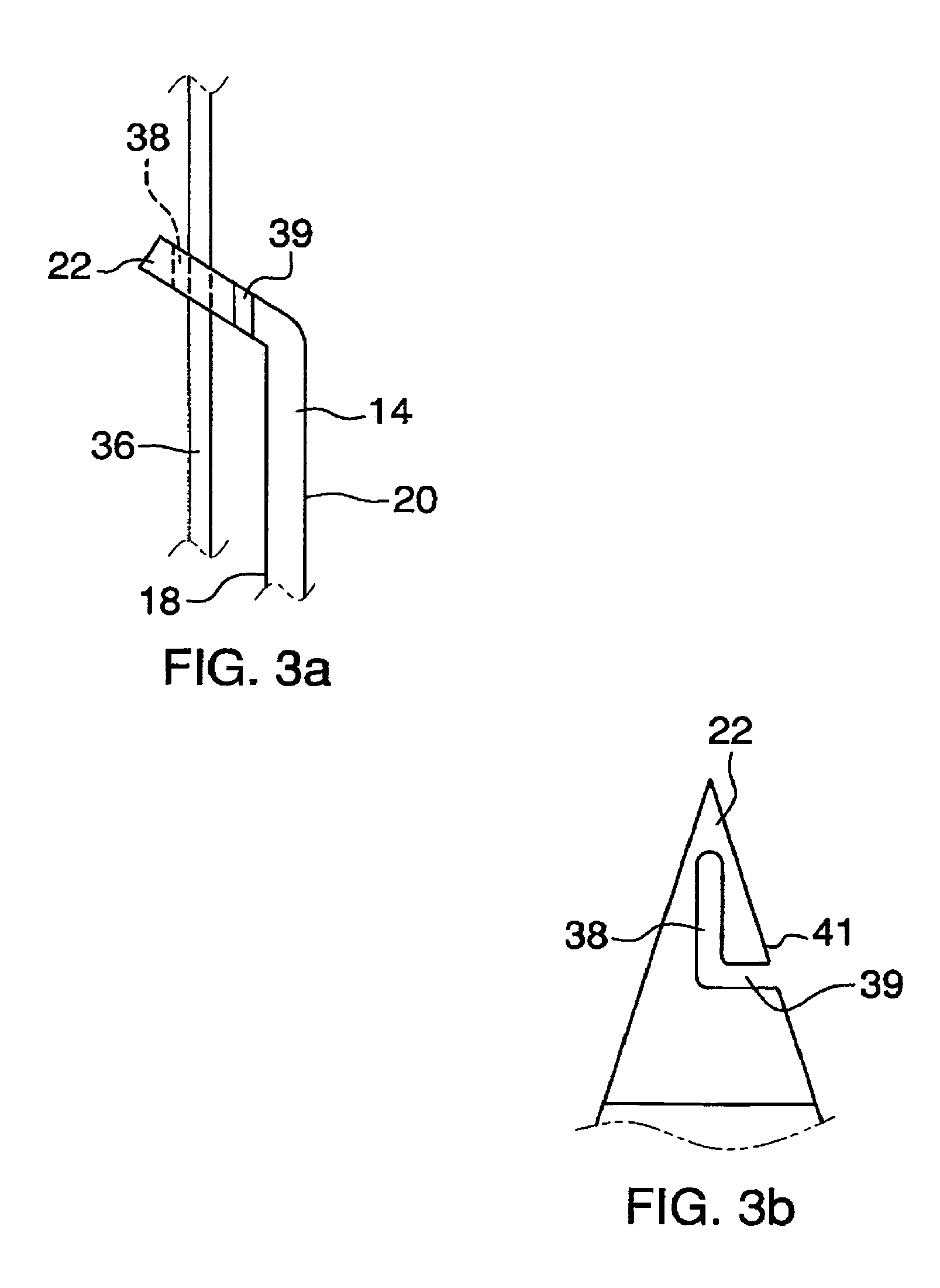
[0024]With reference to FIGS. 1 through 3, there is illustrated a gambrel device 10 in accordance with an embodiment of the invention. Device 10 includes a gambrel 12 having a gambrel frame 14 to which is mounted an electrically powered winch 16. The gambrel frame 14 is comprised of a single plate of steel or similar strong material and has a front side 18 and a back side 20. The gambrel frame 14 is generally triangular-shaped and includes a centrally disposed top apex 22 and oppositely disposed base apexes 24 and 26 each of which are upwardly angled and sharpened to a point. Apexes 24 and 26 provide conventional gambrel hooks or structure utilized to hang an animal for storage and / or processing. The gambrel frame 14 further includes a centrally disposed hook aperture 28 which may be used in suspending or otherwise attaching the device 10 from a support as will be further described hereinafter. Hook aperture 28 may be cross-shaped as illustrated to engage a hook in an upward, downwa...


PUM


Abstract

A gambrel device includes a gambrel frame of a generally tri-angular shaped plate construction of steel or similar strength material that includes a top apex, oppositely disposed base apexes and a substantially flat back surface. A winch is mounted to a front surface of the gambrel frame and includes an electric motor and a winch drum operatively connected to the electric motor for driving the winch drum. A rigging cable extends from the winch drum and is threaded through an eyelet disposed at the top apex of the gambrel frame. The rigging cable may be secured to an existing structure and the winch is operated to hoist and suspend the gambrel frame from the structure. Further, the gambrel device may be utilized as a skid to relocate an animal by dragging the animal across a ground surface.

Description

FIELD OF THE INVENTION[0001]The present invention relates generally to hunting aids including gambrels, game dragging devices and game hoisting devices, and more particularly, relating to portable gambrel device for dragging and hanging an animal from an existing support structure.BACKGROUND OF THE INVENTION[0002]In hunting it is important to dress an animal as soon as possible to prevent spoiling of the animal before the animal can be further processed. Typically, an animal is suspended from its hind legs with the legs spread to permit better access to the animal. A gambrel is a device that is well known to hunters and is used by hunters to suspend an animal from an existing support in the field for dressing. There exist gambrels of a myriad of constructions for solving various problems encountered when attaching an animal to the gambrel and suspending the animal from the gambrel. However, the basic structure of the gambrel has seen little change over the years. An equal challenge ...

Claims


Application Information

Patent Timeline
Patent Type & Authority Patents(United States)
IPC IPC(8): B66D1/00
CPCB66D1/12A22B5/06A22B5/00B66D1/60B66D3/18A22B7/002
Inventor SCOTT, TERRANCE
Owner SCOTT TERRANCE
Learn More