Multi-projection system

a projection system and projection system technology, applied in the field of projection systems, can solve the problems of low limit in that screen has a two-dimensional plane, etc., and achieve the effect of improving the degree of immersion of theater customers in images and enhancing the degree of immersion

Active Publication Date: 2014-05-06
CJ 4DPLEX CO LTD
View PDF24 Cites 15 Cited by
  • Summary
  • Abstract
  • Description
  • Claims
  • Application Information

AI Technical Summary

Benefits of technology

[0011]It is another object of the present invention to provide a multi-projection system that is capable of reproducing images by utilizing various surfaces in a theater such as front, left / right, and top / bottom sides, thereby improving a degree of immersion in the images.
[0012]It is still another object of the present invention to provide a multi-projection system that is capable of correcting images in accordance with the kinds of projection surfaces onto which the images are projected, so that even though the images are reproduced from different projection surfaces, a degree of immersion of theater customers in the images can be enhanced.

Problems solved by technology

Such 3D technology provides three-dimensional images to the theater customers, but they just see the images reproduced on the flat screen, thereby causing their immersion to the images to become low.
However, the conventional technology like the 3D technology or IMAX technology allowing the image immersion of the customers to be improved has a limit in that the screen has a two-dimensional plane.

Method used


Image

  • Multi-projection system
  • Multi-projection system
  • Multi-projection system

Examples


first embodiment

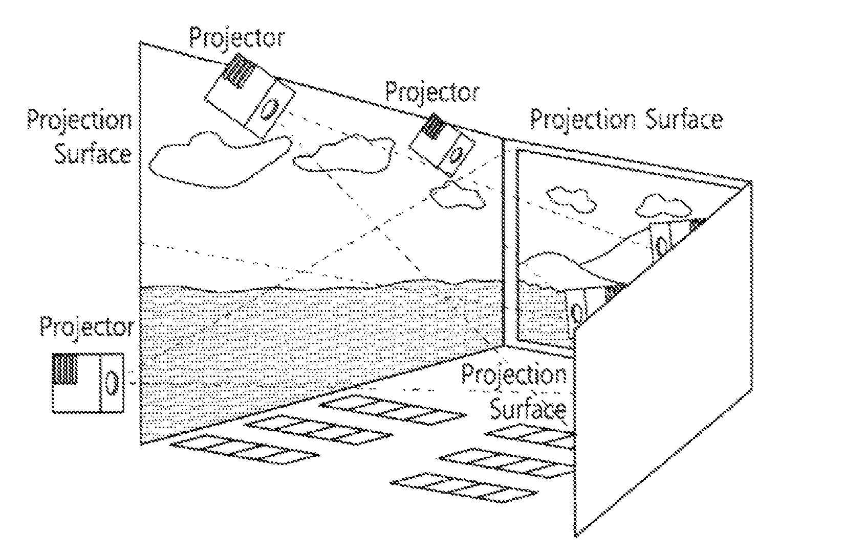
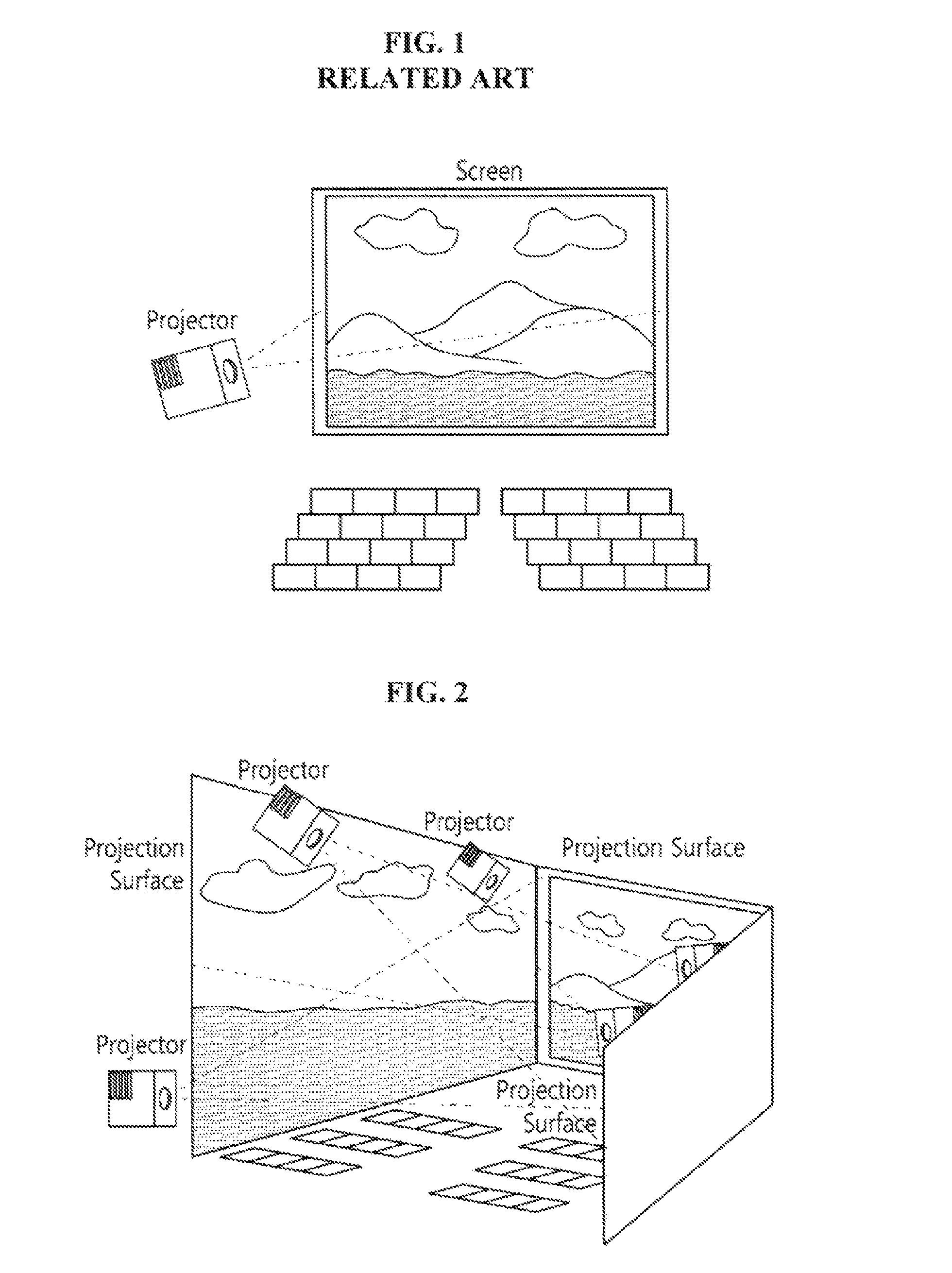
[0030]FIG. 2 is a perspective view showing a multi-projection system according to the present invention.

[0031]A multi-projection system according to a first embodiment of the present invention has a plurality of projection surfaces disposed on two or more sides not parallel to each other.

[0032]In conventional practices, images are projected only onto a screen disposed on the front side of a theater, and the images reproduced on the two-dimensional screen are provided to theater customers. Alternatively, 3D technology is applied to the images reproduced on a flat plane. According to the present invention, however, images are reproduced from the plurality of projection surfaces disposed three-dimensionally on two or more sides not parallel to each other, so that even though the 3D technology is not applied to the images, the images having high three-dimensional effects and immersion can be provided to the theater customers through the three-dimensionally disposed projection surfaces.

[...

second embodiment

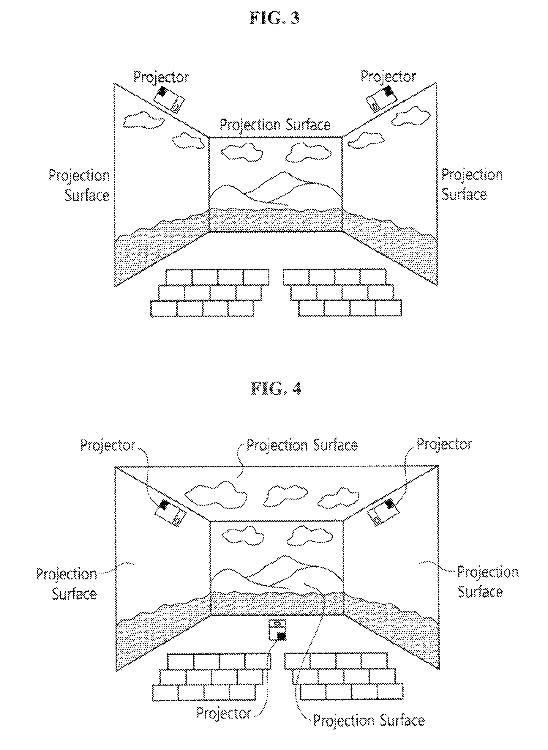
[0046]FIG. 5 shows the projection surfaces disposed on the front, left, right, top and bottom sides. When compared with the present invention as shown in FIG. 4, the projection surface is further disposed on the bottom side. As a result, the images can be reproduced through all of surfaces to which the views of the theater customers are developed. If the projection surfaces are provided as shown in FIG. 5, however, the positions and sizes of the projection surfaces should be adjusted to allow the image on the bottom side to be seen by the theater customers sitting on the rear side seats in consideration of the positions of the seats and the inclination of the arrangement of the seats.

[0047]According to the present invention, it is possible that the number of projection surfaces disposed on each side is provided plurally. According to the present invention, as shown in FIG. 5, one projection surface is disposed on each of the front, left, right, top and bottom sides. However, the num...


PUM


Abstract

A multi-projection system having a plurality of projection surfaces onto which images are projected is provided, where the plurality of projection surfaces are disposed on two or more sides not parallel to each other. The multi-projection system provides high three-dimensional images and a high degree of immersion in images and further provides multi-view images, thereby making theater customers feel like they really exist in the space described through the images.

Description

BACKGROUND OF THE INVENTION[0001]1. Field of the Invention[0002]The present invention relates to a projection system that projects and reproduces images, and more particularly, to a multi-projection system that has a plurality of projection surfaces three-dimensionally disposed therein to project images onto the three-dimensionally disposed projection surfaces, thereby providing the three-dimensional images to theater customers.[0003]2. Background of the Related Art[0004]So as to reproduce images like movies, advertisements, etc. in a theater, conventionally, two-dimensional images have been projected onto a flat screen disposed on the front side of the theater.[0005]FIG. 1 shows an example wherein an image is reproduced in a conventional theater system, and in this case, the image is projected from a projector disposed at the rear side of a theater onto the screen disposed on the front side of the theater, so that only two-dimensional image is provided to the theater customers.[000...

Claims


Application Information

Patent Timeline
Patent Type & Authority Patents(United States)
IPC IPC(8): G03B37/04G03B21/26
CPCG02B27/2271G03B21/56H04N9/3147E04H3/22H04N9/3185G03B21/26H04N9/3182A47C1/12G03B37/04G03B31/00G03B21/14G03B29/00G03B21/206A47C3/18G03B21/2053G03B21/003G03B21/60H04N9/3194G03B21/608G03B21/16G03B41/00A63J25/00A63J2005/002G03B35/20H04N21/4122G02B30/50H04N21/47H04N21/4316
Inventor CHOI, YOO HWANSEONG, IN JAEKIM, HWAN CHULKANG, SU RYEON
Owner CJ 4DPLEX CO LTD
Why Eureka
Try Eureka