Eureka AIR delivers breakthrough ideas for toughest innovation challenges, trusted by R&D personnel around the world.

Inner link plate for bicycle chain

a technology of inner link plate and bicycle chain, which is applied in the direction of driving chains, belts/chains/gearrings, chain elements, etc., can solve the problems of narrow chain, wide space between the inside surfaces of inner link plates where the teeth are, and the shifting of sprockets to the next sprock

Active Publication Date: 2014-05-27
SHIMANO INC
View PDF12 Cites 28 Cited by
  • Summary
  • Abstract
  • Description
  • Claims
  • Application Information

AI Technical Summary

Benefits of technology

The invention aims to create a more space between the inside surfaces of inner link plates, even if the width of the bicycle chain is narrowed. Additionally, the inner link plate has a recess on its inside surface, which helps the teeth of a sprocket smoothly enter the space between two inner link plates during shifting between sprockets. These features improve the performance of the chain transmission system in bicycles.

Problems solved by technology

As the number of rear sprockets increased, this situation has resulted in the chain becoming narrower.
It has been discovered that using a narrower chain may present problems in shifting from one sprocket to the next sprocket.
For example, one potential problem of using narrow chain is that the widths of the spaces between the inside surfaces of the inner link plates where the teeth of the sprockets enter the inner link becomes too narrow.
As a result, the inside surfaces of the inner link plates may undesirably catch on the teeth of the sprockets during shifting from one sprocket to the next sprocket

Method used


Image

  • Inner link plate for bicycle chain
  • Inner link plate for bicycle chain
  • Inner link plate for bicycle chain

Examples


Embodiment Construction

[0020]Selected embodiments will now be explained with reference to the drawings. It will be apparent to those skilled in the art from this disclosure that the following descriptions of the embodiments are provided for illustration only and not for the purpose of limiting the invention as defined by the appended claims and their equivalents.

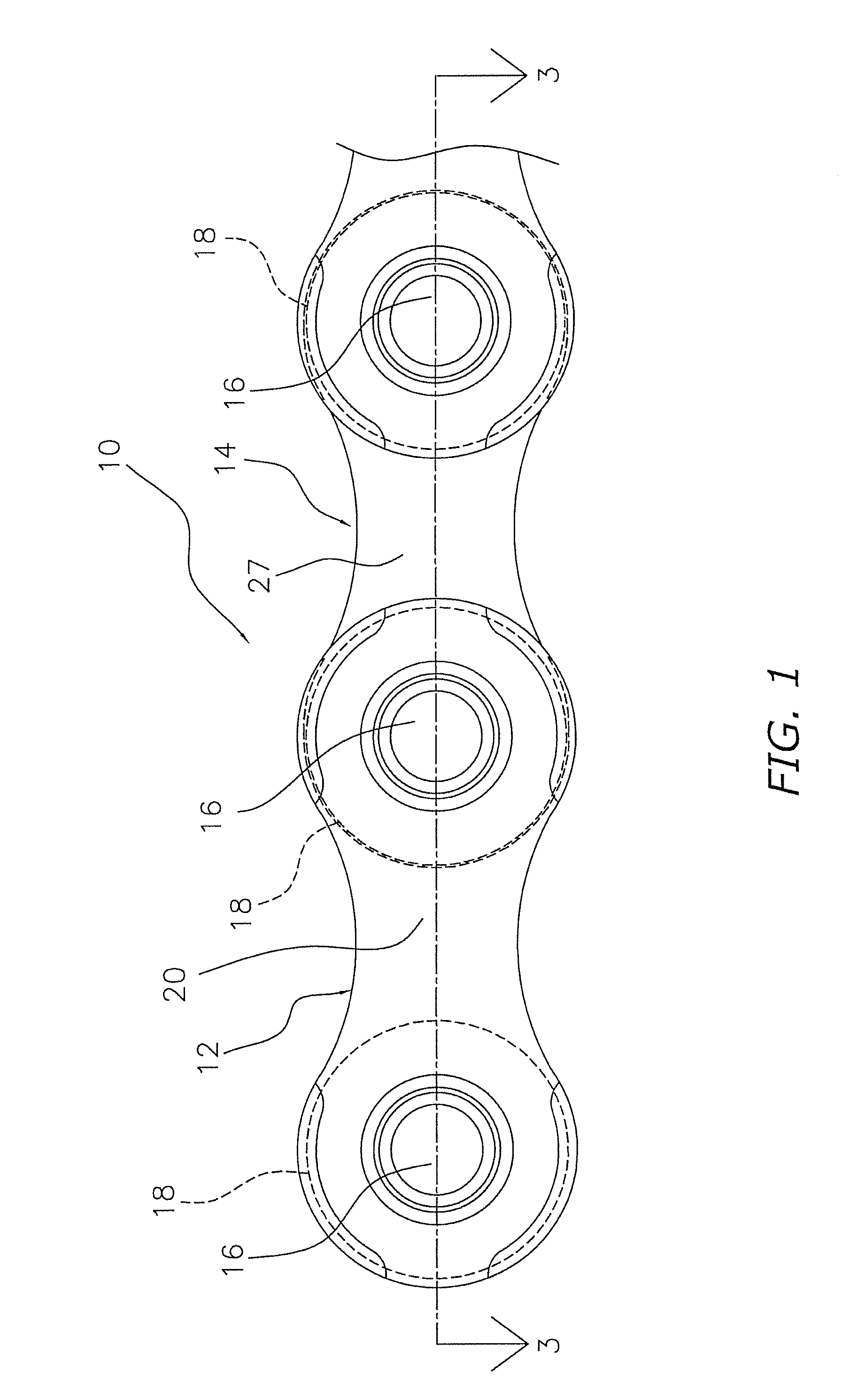
[0021]Referring initially to FIG. 1, a portion of a bicycle chain 10 is illustrated in accordance with a first embodiment. As used herein to describe the parts of the bicycle chain 10, the following directional terms “inside”, “outside”, “inner”, “outer”, “above”, “below”, “width”, and “longitudinal” as well as any other similar directional terms refer to those directions relative to the bicycle chain 10 in an installed position on a bicycle that is upright on a horizontal surface.

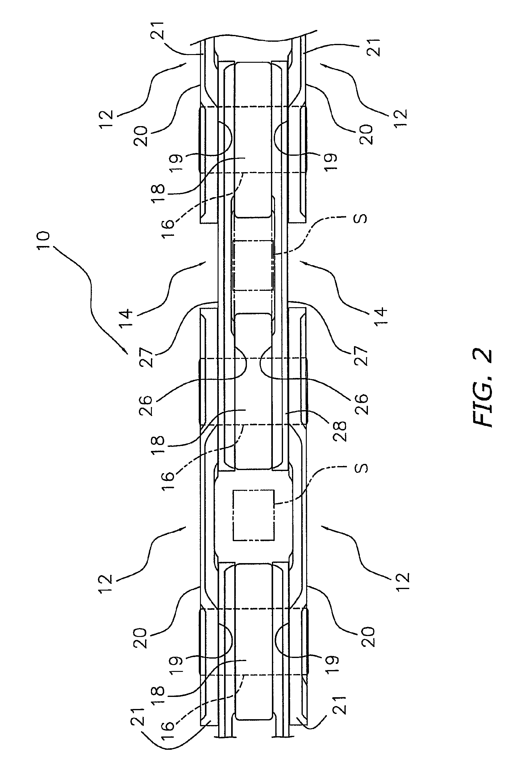
[0022]The bicycle chain 10 basically includes a plurality of outer link plates 12, a plurality of inner link plates 14 and a plurality of connecting pins or rivets 16 an...


PUM


Abstract

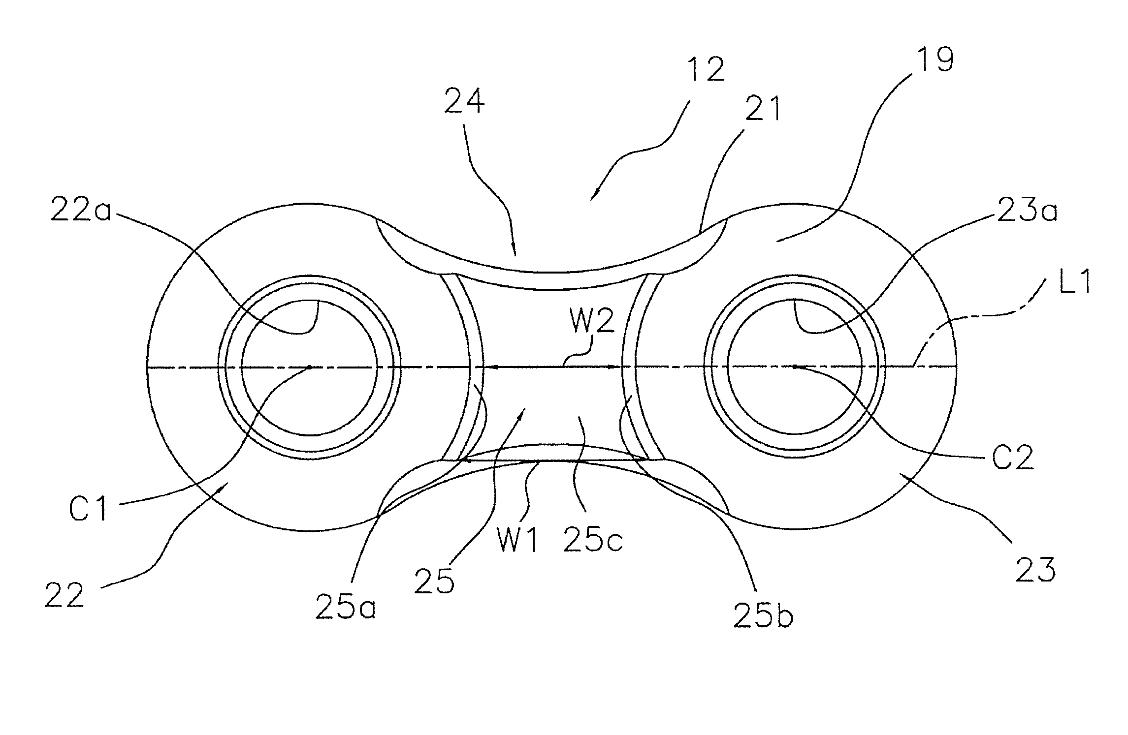
An inner link plate is provided for a chain. The inner link plate has a longitudinal centerline, an inside surface arranged to face another inner link plate when the chain is assembled, an outside surface opposite to the inside surface, and an outer peripheral edge disposed between the inside and outside surfaces. The bicycle inner link plate basically has a first end portion, a second end portion and a connecting portion. The first and second end portions are each provided with a connecting opening. The connecting portion includes a recess disposed on the inside surface of the connecting portion. The recess has a maximum longitudinal width on the outer peripheral edge, and a minimum longitudinal width in a region adjacent the longitudinal centerline. The recess at least extends from the outer peripheral edge to the longitudinal centerline.

Description

BACKGROUND[0001]1. Field of the Invention[0002]This invention generally relates to a configuration of an inner link plate for a bicycle chain. More specifically, the present invention relates to an inner link plate for a bicycle chain that is used in a bicycle that shifts between sprockets to change gears.[0003]2. Background Information[0004]Most bicycles have a drive train that uses a chain to transmit the pedaling action from the rider to the rear wheel. Bicycle chains have a plurality of inner links and a plurality of outer links that are interconnected in an alternating manner by a plurality of pins. Typically, each of the inner links includes a pair of parallel inner plates connected by a pair of parallel hollow cylinders or pins surrounded by cylindrical rollers. Each of the outer links includes a pair of parallel outer plates connected by the pins of the adjacent inner links. In order to form a single continuous chain, two of the inner links are connected together by a releas...

Claims


Application Information

Patent Timeline
Patent Type & Authority Patents(United States)
IPC IPC(8): F16G13/06F16G13/02
CPCF16G13/06
Inventor OISHI, TOSHINARIFUKUMORI, TSUYOSHIEMURA, ATSUHIRO
Owner SHIMANO INC
Why Eureka
Eureka Blog
Learn More