Semiconductor light-emitting device with tunable emission wavelength
Inactive Publication Date: 2009-04-09
SUMITOMO ELECTRIC IND LTD
View PDF10 Cites 31 Cited by
Summary
Abstract
Description
Claims
Application Information
AI Technical Summary
This helps you quickly interpret patents by identifying the three key elements:
Problems solved by technology
Method used
Benefits of technology
[0015]In another feature of the present invention, the optical grating may be a chirped grating with periods of the refractive index linearly increasing from an end of the optical grating to the other end thereof. The specific electrodes may change the refractive index of a portion of the chirped grating covered by the specific electrodes and the composite reflection spectrum of the optical reflector shows the single peak. Thus, the light-emitting device may select one of the transmission maxima in the transmission spectrum of the ring resonator by the optical grating of the optical reflector without using the vernier effect. Because the reflection peak in the composite spectrum of the optical reflector shows relatively wide width, thus selected emission wavelength of the light-emitting device may be stable during the operation of the device.
[0016]Moreover, the optical reflector of the present invention may adjust not only the wavelength of the reflection maximum but also the maxim
Problems solved by technology
However, such coupler causes an optical loss by a few decibels (dB) per one coupling, which increases the threshold level for the laser operation and reduces the emission efficiency, namely the slope efficiency, of the laser device.
Moreover, the decrease of the maximum reflectance of respective peaks of the SG-grating is relatively large, which restricts the available wavelength range for the laser oscillat
Method used
Image
Click on the blue label to locate the original text in one second.
Reading with bidirectional positioning of images and text.
Examples
first embodiment
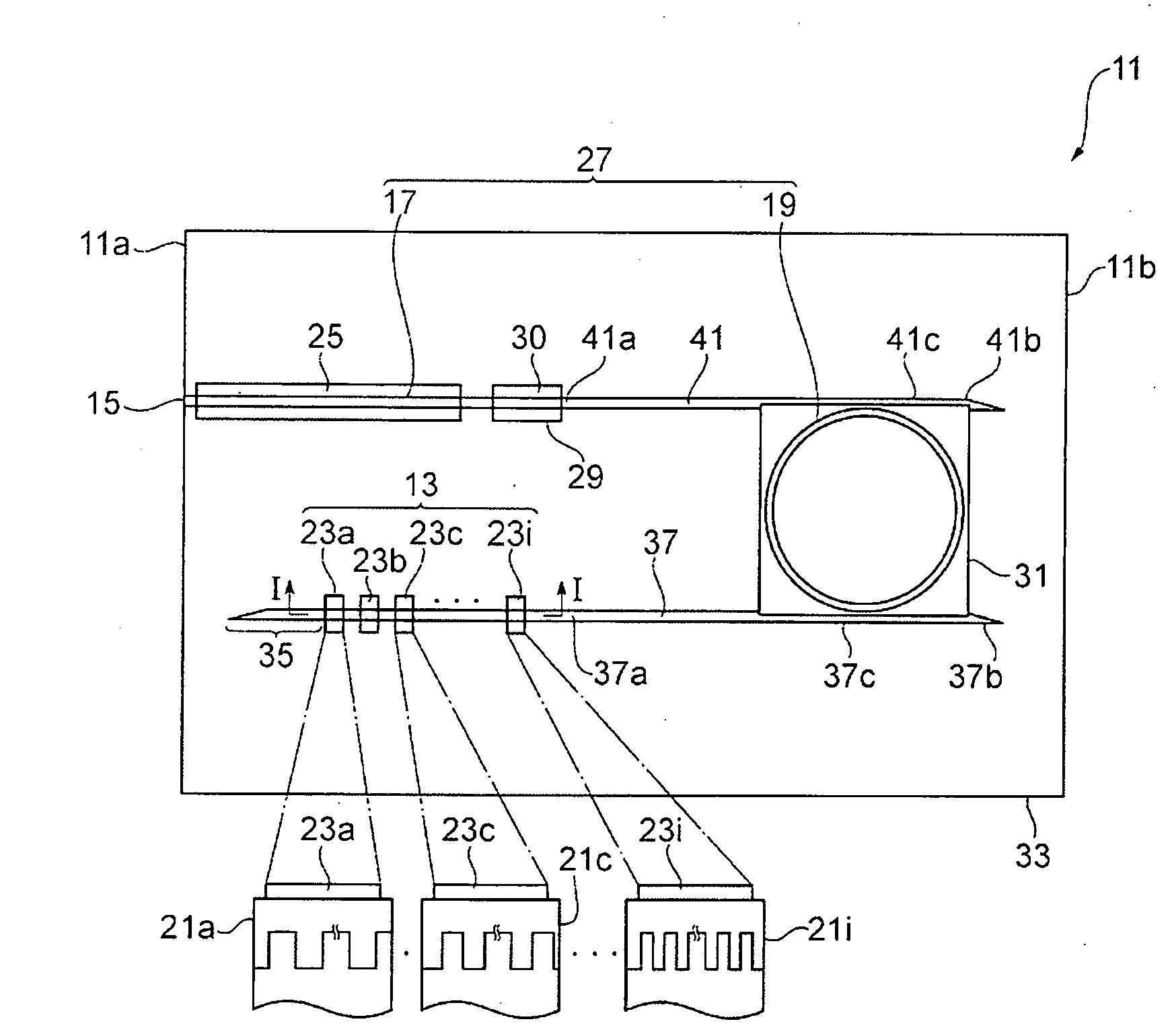
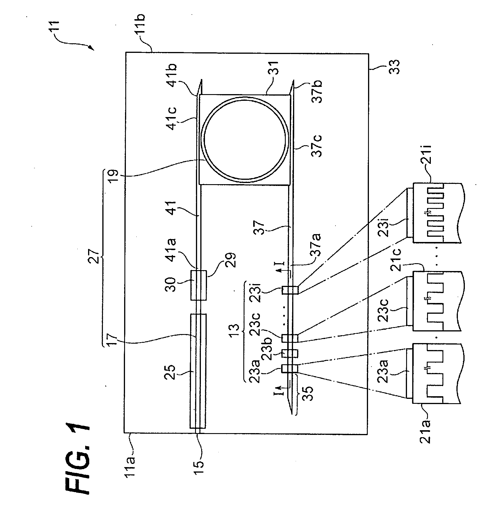
[0036]FIG. 1 schematically illustrates a semiconductor light-emitting device 11 according to an embodiment of the present invention. A feature of the present device is that the output wavelength emitted therefrom may be tunable. The device 11 includes an optical reflector 13, a reflective end 15, a gain waveguide 17, and a ring resonator 19. These elements are formed on a semiconductor substrate.
[0037]The optical reflector 13 includes a plurality of diffraction gratings, 21a, 21c and 21i, each having independent electrodes, 23a to 23c and 23i. FIG. 1 includes magnified views of respective gratings, 21a, 21c and 21i, each taken along the line I-I. The period of the gratings, 21a, 21c and 21i, are different from each other. The electrodes, 23a, 23c and 23i, are accompanied with respective gratings, 21a, 21c and 21i.
[0038]One end surface 11a of the semiconductor substrate forms the reflective end 15. The gain waveguide 17 has an optical gain due to the carrier injection from the elect...
second embodiment
[0079]FIG. 11 illustrates a light-emitting device according to the second embodiment of the present invention. The light-emitting device 111 of the present embodiment provides, on the semiconductor substrate, an optical reflector 113, a reflective end 15, a gain waveguide 17 and a ring resonator 19. The elements without the optical reflector 113 have the same configurations with those of the first embodiment. The optical reflector 113 includes a chirped grating 121 and a plurality of electrodes, 123a, 123b, 123c, and 123i. FIG. 11 includes a sectional view that schematically illustrates the chirped grating 121 taken along the ling I-I.
[0080]The electrodes, 123a to 123i, are arranged along the primary axis of the chirped grating 121. The chirped grating 121 has a characteristic that the period of the refractive index linearly varies depending on the position. For instance, the chirped grating 121 includes a grating segment 121a with a period of the refractive index of Λa, a grating s...
PUM
Abstract
The present invention is to provide a semiconductor light-emitting device with a variable output wavelength that reduces the wavelength dependence of the optical output power. The light-emitting device provides an optical cavity defined by a reflective end and a reflector. The gain waveguide and the ring resonator are set within the cavity. The reflector comprises a plurality of gratings each accompanied with an electrode. The periodicity of the refractive index in respective gratings is different from each other. The ring resonator shows a plurality of transmission maxima. The light-emitting device emits light with a wavelength defined by the transmission maxima of the ring resonator and the enhanced reflectivity region adjusted by the bias applied to electrodes of the optical reflector.
Description
BACKGROUND OF THE INVENTION[0001]1. Field of the Invention[0002]The present invention relates to a semiconductor light-emitting device.[0003]2. Related Prior Art[0004]Matsuo et al. disclosed a wavelength variable laser in IEEE International Semiconductor Laser Conference 2006 TuB2, titled by “Widely tunable laser using micro ring resonators.” This wavelength variable laser included two ring resonators. Specifically, the wavelength variable laser had two facets opposite to each other forming the laser resonator. In order to realize the wavelength variable function, the laser formed within the laser resonator two ring resonators with different radii to each other. Varying the current injected into these ring resonators, the refractive index thereof was changed, which resulted in the change of the resonant wavelength of the ring resonator.[0005]Two ring resonators had a function of a wavelength variable filter. Each ring resonator inherently had a transmission spectrum with a period sp...
Claims
Application Information
Patent Timeline
Application Date:The date an application was filed.
Publication Date:The date a patent or application was officially published.
First Publication Date:The earliest publication date of a patent with the same application number.
Issue Date:Publication date of the patent grant document.
PCT Entry Date:The Entry date of PCT National Phase.
Estimated Expiry Date:The statutory expiry date of a patent right according to the Patent Law, and it is the longest term of protection that the patent right can achieve without the termination of the patent right due to other reasons(Term extension factor has been taken into account ).
Invalid Date:Actual expiry date is based on effective date or publication date of legal transaction data of invalid patent.