Locking assembly for a drainage catheter

a technology of locking mechanism and drainage catheter, which is applied in the direction of catheters, wound drains, suction devices, etc., can solve the problems of catheter being easily pulled out, device being somewhat uncomfortable for patients, and potential for severe infections

Active Publication Date: 2014-05-27
COOK MEDICAL TECH LLC
View PDF35 Cites 18 Cited by
  • Summary
  • Abstract
  • Description
  • Claims
  • Application Information

AI Technical Summary

Benefits of technology

[0006]In a first aspect, a locking assembly for use with a tension member in a drainage catheter includes a connector, a locking arm, and a locking mechanism. The connector is disposed at a proximal end of the catheter and has an exterior surface profile and a passageway extending longitudinally therethrough. The locking arm has an interior surface profile that corresponds with the exterior surface profile of the connector and is pivotably attached to the connector to enable pivoting movement of the locking arm about an axis of rotation, to and between an unlocked position and a locked position whereby when the locking arm is in the locked position, the tension member is secured between the interior surface of the locking arm and the exterior surface of the connector. The locking mechanism prevents the locking arm from inadvertently disengaging from the locked position.
[0008]In a second aspect of the invention, a drainage catheter includes an elongated tubular member and a locking assembly. The tubular member has a distal end for insertion into a patient, a proximal end, and a passageway extending longitudinally therethrough. The distal end is formed to be positioned into a desired configuration. The locking assembly is engaged with the proximal end of the tubular member and includes a connector, a locking arm, and a locking mechanism. The connector has an exterior surface profile and a passageway extending longitudinally therethrough. The locking arm has an interior surface profile that corresponds with the exterior surface profile of the connector and is pivotably attached to the connector to enable pivoting movement of the locking arm about an axis of rotation, to and between an unlocked position and a locked position whereby when the locking arm is in the locked position, a tension member is secured between the interior surface of the locking arm and the exterior surface of the connector. The locking mechanism prevents the locking arm from inadvertently disengaging from the locked position.
[0011]In an additional feature of this aspect, the locking mechanism includes an interference fit between the interior surface of the sleeve and the exterior surface of the connector. In a further feature of this aspect, the locking assembly is dimensioned to fit within a 30 Fr access sheath. In other features, the connector may include an aperture through which a proximal portion of the tension member may pass and the sleeve may include a sealing element disposed on the interior surface thereof, wherein the sealing element is located such that it prevents any fluid contents of the catheter from inadvertently exiting the aperture when the sleeve is in the locked position.

Problems solved by technology

However, one problem with these catheters is that the catheter can be easily pulled out by movement of the body or by the emptying of, for example, the bladder.
Another problem is that side ports at the distal end of the catheter may be inadvertently drawn into the abdominal cavity, creating the potential for severe infections.
Although the locking drainage catheter is well-suited for its intended purpose, the lockable connector portion of the catheter is somewhat bulky, which may make the device somewhat uncomfortable for a patient and which prevents the device from being used with relatively smaller sized access sheaths (e.g., a 30 Fr access sheath) unless the access sheath is altered or modified.

Method used


Image

  • Locking assembly for a drainage catheter
  • Locking assembly for a drainage catheter
  • Locking assembly for a drainage catheter

Examples


Embodiment Construction

[0029]For the purposes of promoting an understanding of the principles of the invention, reference will now be made to the embodiments illustrated in the drawings, and specific language will be used to describe the same. It should nevertheless be understood that no limitation of the scope of the invention is thereby intended, such alterations and further modifications in the illustrated apparatus, and such further applications of the principles of the invention as illustrated therein being contemplated as would normally occur to one skilled in the art to which the invention relates.

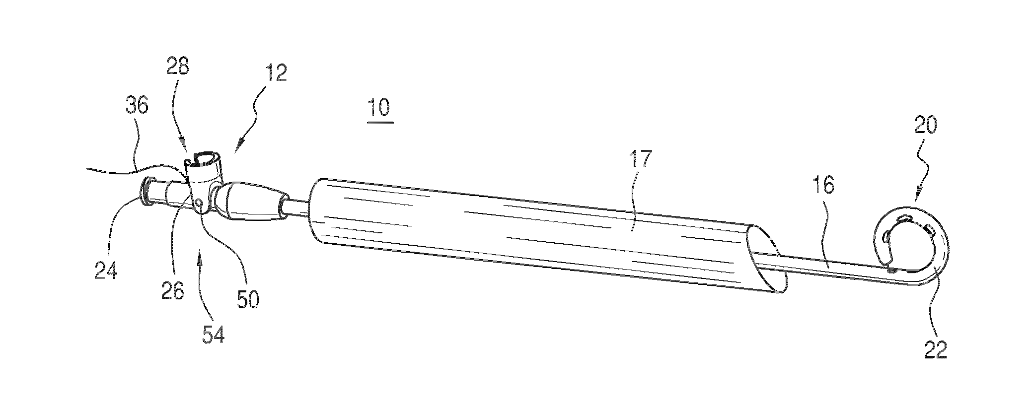
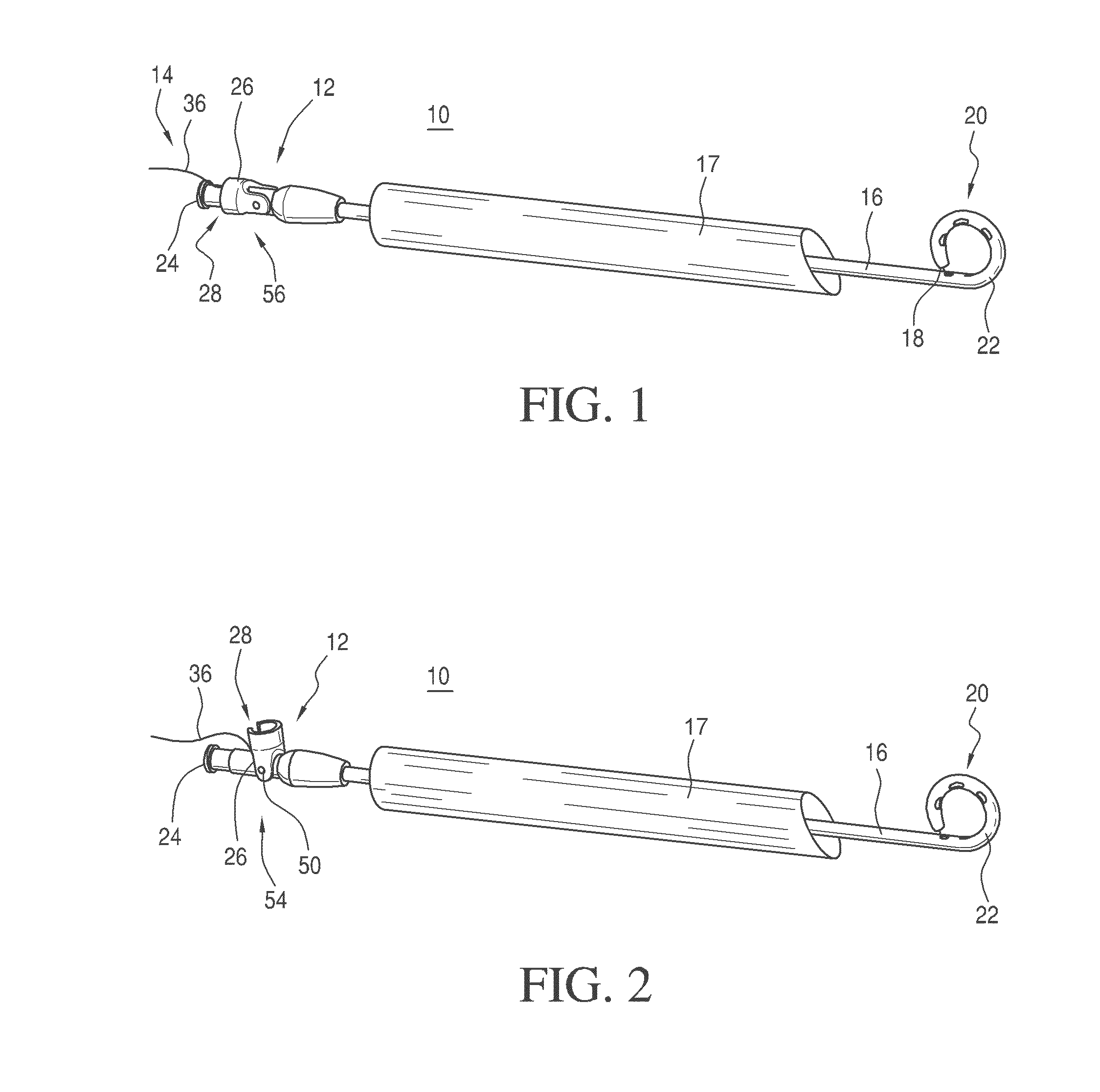
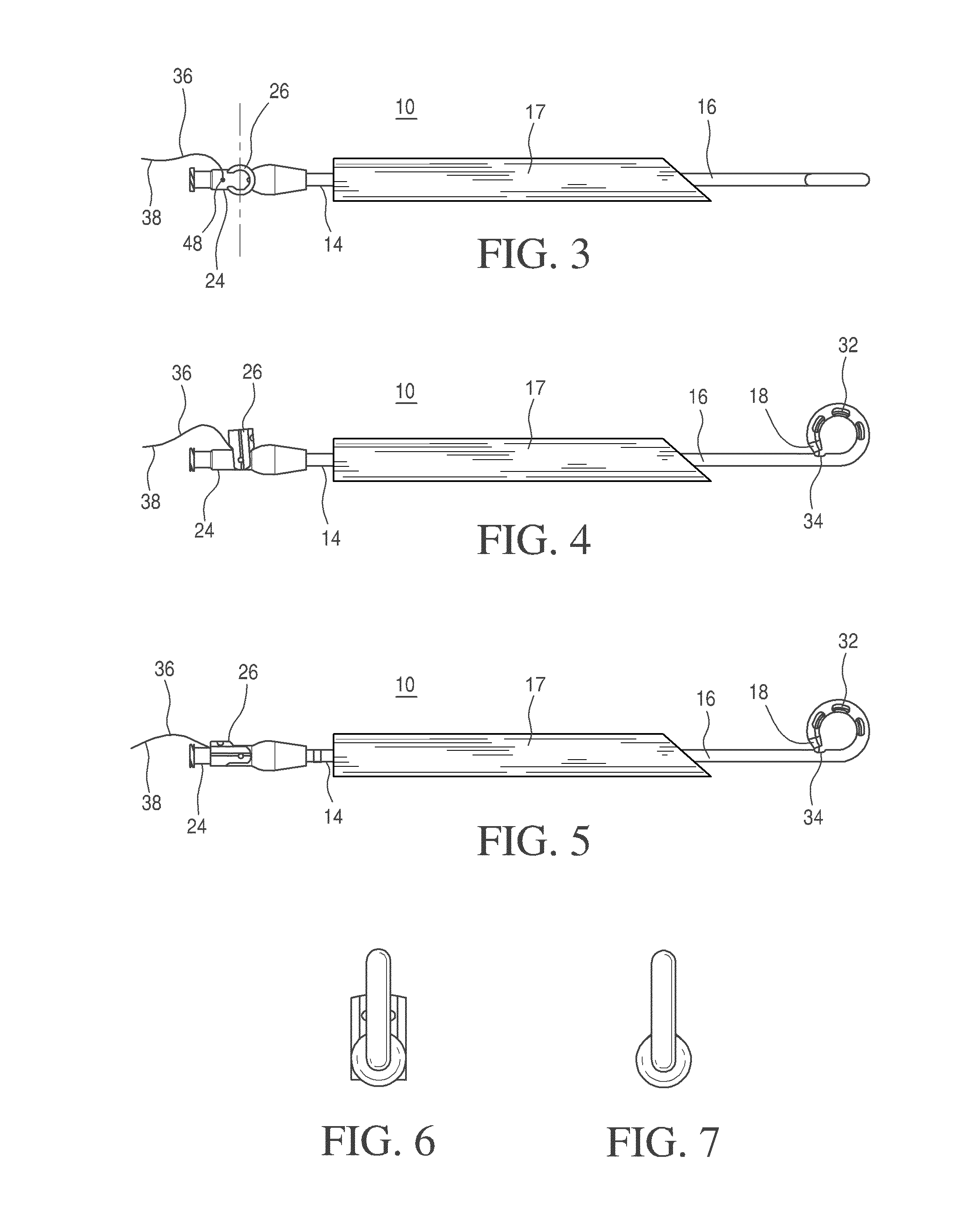
[0030]In the following discussion, the terms “proximal” and “distal” will be used to describe the opposing axial ends of the drainage catheter, as well the opposing axial ends of component features of the catheter, such as the locking mechanism. The term “proximal” is used in its conventional sense to refer to the end of the catheter or component feature that is closest to the operator during use. The ter...


PUM


Abstract

A drainage catheter includes an elongated tubular member, a locking assembly engaged with a proximal end of the tubular member, and a tension member for drawing a distal end of the tubular member into a desired configuration. The locking assembly includes a connector, a locking arm, and a locking mechanism. The connector has an exterior surface profile that corresponds with an interior surface profile of the locking arm. The locking arm is pivotably attached to the connector to enable pivoting movement of the locking arm between an unlocked position and a locked position whereby the tension member is secured between the locking arm and the connector when the arm is in the locked position. The locking assembly may alternatively comprise a connector and a sliding sleeve or a connector having a clamping element disposed therein.

Description

RELATED APPLICATIONS[0001]This application claims the benefit of U.S. Provisional Application No. 61 / 254,012, filed Oct. 22, 2009, the entire content of which is hereby incorporated by reference herein.TECHNICAL FIELD[0002]This invention relates to drainage catheters and particularly to a locking mechanism for a drainage catheter for drawing and maintaining the distal end of the catheter into a desired configuration.BACKGROUND[0003]Suprapubic catheterization of the bladder is used to drain the bladder after surgery or when the genitourinary system is plugged by an obstruction. Other percutaneously inserted catheters are also used to drain the kidney or biliary system as well as to drain abscesses, other sites of fluid collection, and other viscera. Still other percutaneously inserted catheters are gastrostomy feeding tubes.[0004]These catheters are typically introduced into the patient by means of a large hypodermic needle or trocar, which pierces the abdominal wall. A wire guide is...

Claims


Application Information

Patent Timeline
Patent Type & Authority Patents(United States)
IPC IPC(8): A61M27/00
CPCA61M2027/004A61M25/04A61M2025/0163
Inventor AHMED, MAHFUZABUNCH, TYLER J.AGNEW, CHARLES W.DUNCAN, KATEHUNT, JAMES B.NICKLESS, BONITA L.HUTCHINSON, NANCY L.
Owner COOK MEDICAL TECH LLC
Why Eureka
Try Eureka