Systems using eye mounted displays

a technology of eye-mounted displays and electronic devices, applied in the field of eye-mounted display systems, can solve the problems of reducing the ability to see through, reducing the range of vision, and requiring brightness, so as to avoid or reduce interference, avoid or reduce interference

Active Publication Date: 2014-07-22
TECTUS CORP
View PDF40 Cites 295 Cited by
  • Summary
  • Abstract
  • Description
  • Claims
  • Application Information

AI Technical Summary

Benefits of technology

[0014]The present invention overcomes various limitations of the prior art by coupling devices to display devices mounted on and / or inside the eye. The eye mounted display contains multiple sub-displays, each of which projects light to different targeted portions of the retinal surface, in the aggregate forming a virtual display image. These sub-displays utilize optical properties of the eye to avoid or reduce interference between different sub-displays and, in many cases, also to avoid or reduce interference with the natural vision through the eye.
[0016]Nature produces images on the human eye through interaction of visible light wavefronts from the sun with physical objects. Man made displays produce images on the human eye either through the direct generation of visible light wavefronts (Plasma, CRT, LED, SED, etc.), front or rear projection onto screens (DMD™, LCOS, LCD, CRT, laser, etc.), or reflection of light (LCD, liquid paper, etc.). However, these displays all have defects as previously noted. Mounting the display on the head of the viewer (Head Mounted Displays: HMDs) reduces the required brightness, but introduces limits on linearity of optics, resolution, field of view, abilities for “see-through”, weight, cost, etc.
[0023]There are many advantages of eye mounted displays. Depending on the embodiment, some of the advantages can include variable resolution displays where the number of pixels in the display is significantly less than prior art non-eye mounted displays for the same effective resolution; very low brightness required of the display (literally as low as a few thousand photons per retinal cone, approximately one million times less photons than a 2,000 lumen video projector); extremely small size and inherent portability (e.g. worn as a contact lens, and / or implanted within the eye, etc.); extremely high resolution and wide field of view; and potentially lower cost compared to the set of multiple displays that can be replaced by one eye mounted display.

Problems solved by technology

However, these displays all have defects as previously noted.
Mounting the display on the head of the viewer (Head Mounted Displays: HMDs) reduces the required brightness, but introduces limits on linearity of optics, resolution, field of view, abilities for “see-through”, weight, cost, etc.
However, a direct physical implementation of the geometry of FIG. 57 is impractical.

Method used


Image

  • Systems using eye mounted displays
  • Systems using eye mounted displays
  • Systems using eye mounted displays

Examples


Embodiment Construction

Outline

I. Overview

II. Some Definitions and Descriptions

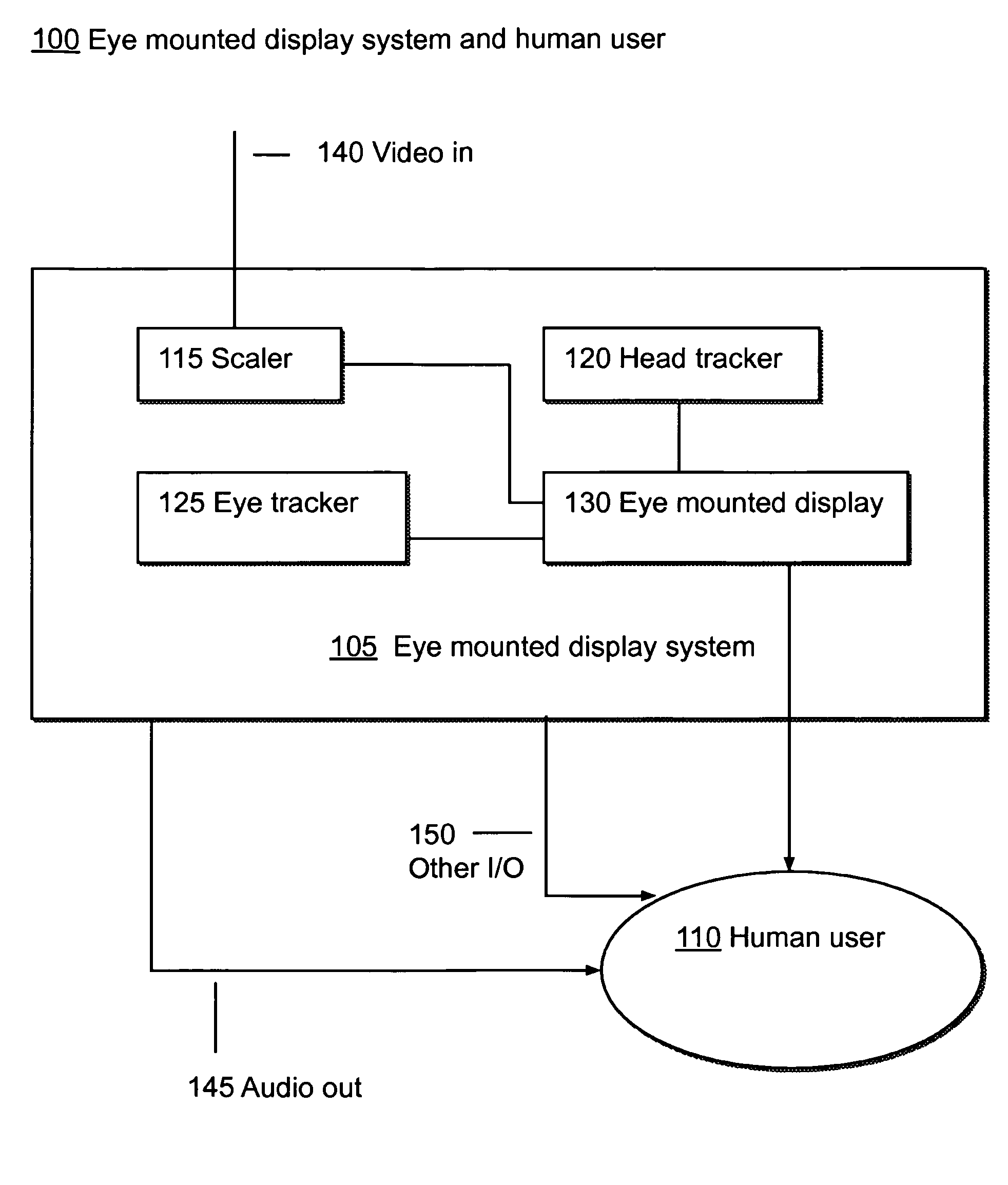
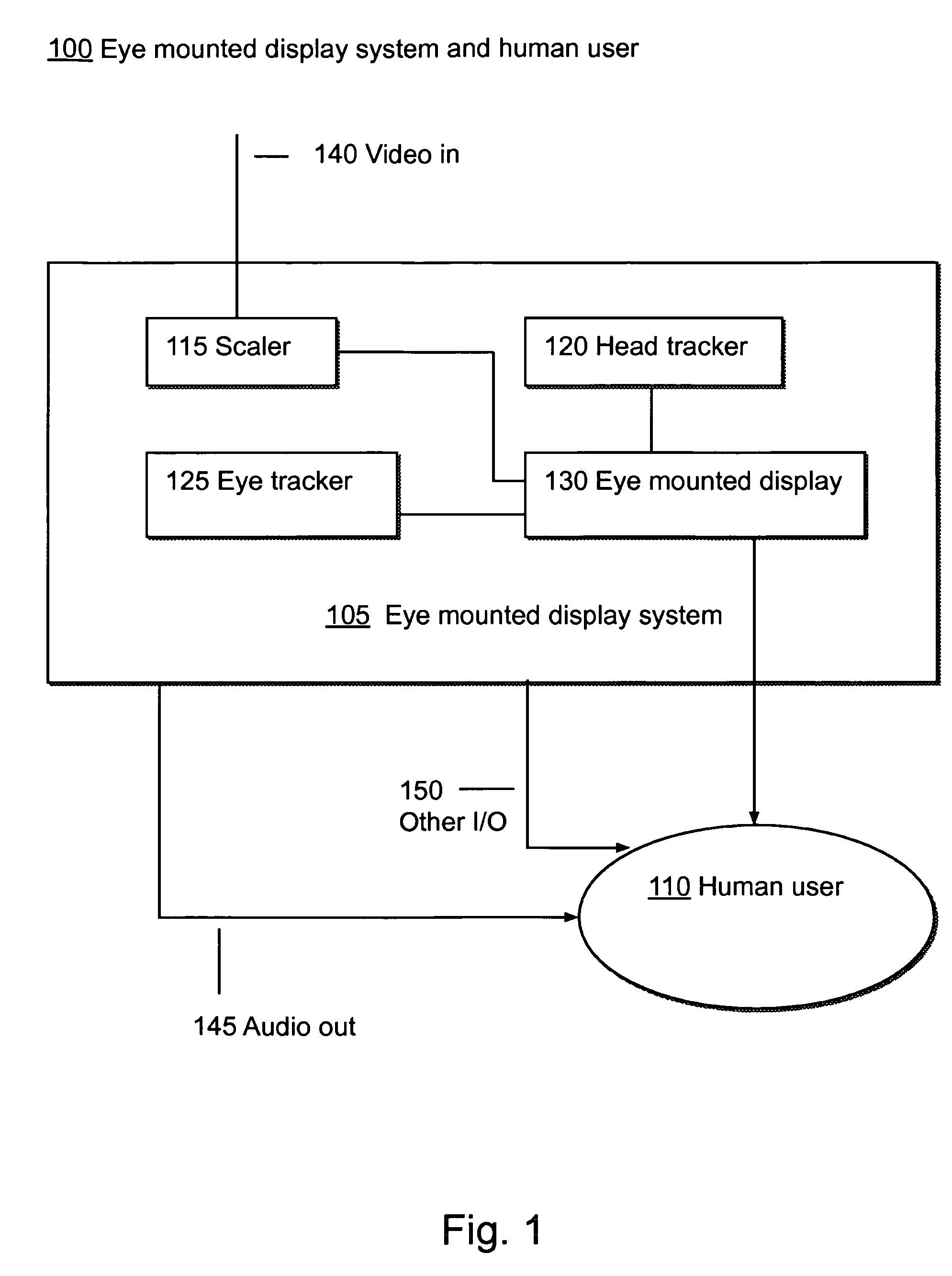
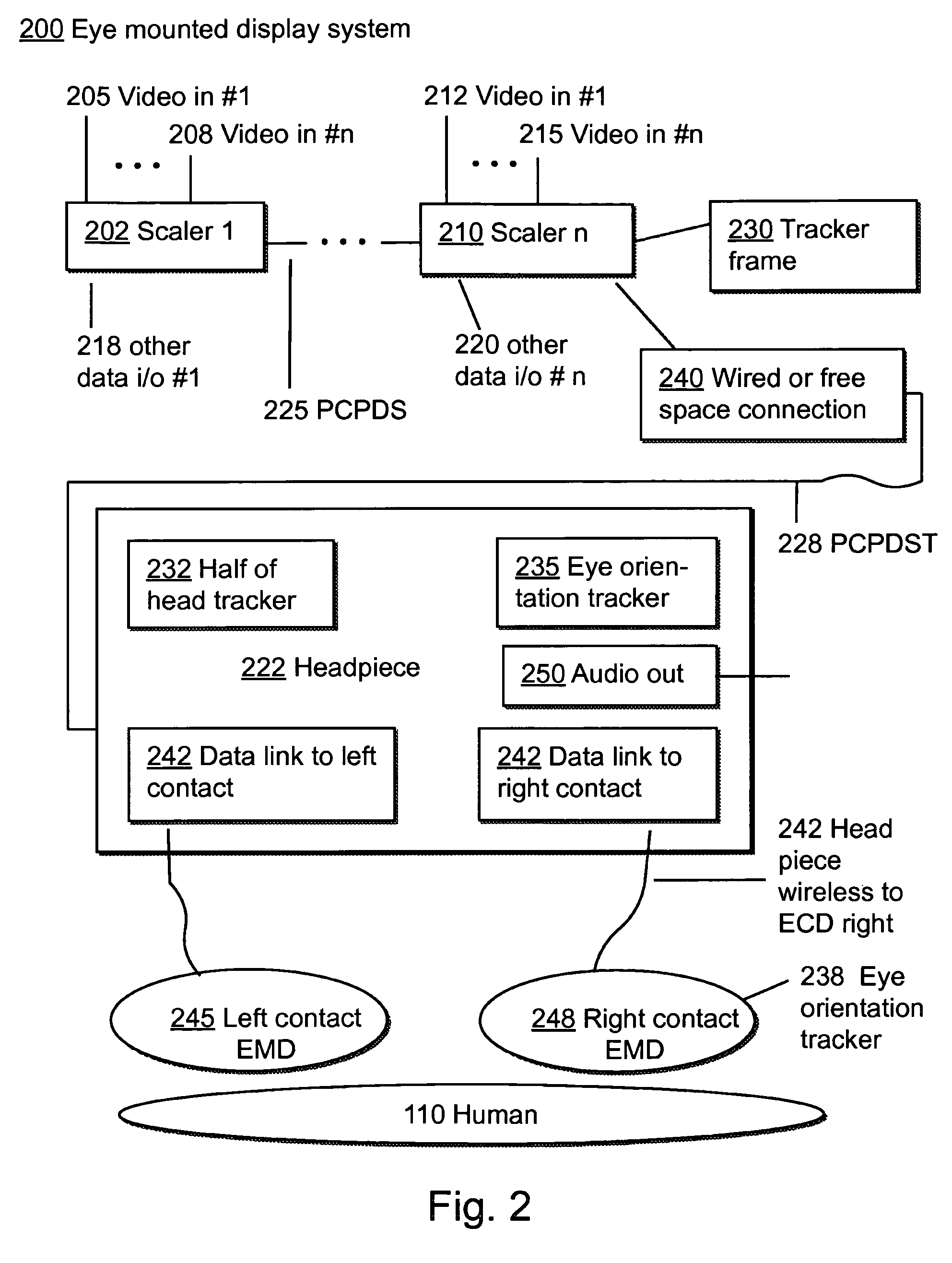
[0110]II.A. Types of Eye Mounted Displays[0111]II.B. Further Descriptions of Eye Mounted Displays[0112]II.C. Components of an Eye Mounted Display System

III. Making Electronics Devices Eye Mounted Display “Aware”[0113]III.A. Simple Example: An Eye Mounted Display Aware Digital Still Camera[0114]III.B. Modifying the EMDS Scaler Hardware[0115]III.C. Eliminating the Head-Tracker[0116]III.D. EMD Awareness: Resolution[0117]III.E. EMD Awareness: Wide Field of View Aware[0118]III.F. EMD Awareness: Stereo[0119]III.G. EMD Awareness: Head Tracking[0120]III.H. EMD Awareness: Augmented Reality[0121]III.I. EMD Awareness: Virtual Reality[0122]III.J. EMD Awareness: Eye Tracker[0123]III.K EMD Awareness: Additional Object Tracking[0124]III.L. EMD Awareness: Pseudo Cone Pixel Data Stream

IV. Product Classes Combining Electronics Devices and EMDSs[0125]IV.A. EMD Aware Digital and Film Still and Motion Cameras[0126]IV.B. EMD Aware Stereo and Multi-Ch...


PUM


Abstract

A display device is mounted on and / or inside the eye. The eye mounted display contains multiple sub-displays, each of which projects light to different retinal positions within a portion of the retina corresponding to the sub-display. The projected light propagates through the pupil but does not fill the entire pupil. In this way, multiple sub-displays can project their light onto the relevant portion of the retina. Moving from the pupil to the cornea, the projection of the pupil onto the cornea will be referred to as the corneal aperture. The projected light propagates through less than the full corneal aperture. The sub-displays use spatial multiplexing at the corneal surface. Various electronic devices interface to the eye mounted display.

Description

CROSS-REFERENCE TO RELATED APPLICATION(S)[0001]This application (a) claims priority under 35 U.S.C. §119(e) to U.S. Provisional Patent Application Ser. No. 61 / 023,833, “Systems using eye mounted displays,” filed Jan. 26, 2008 and (b) is a continuation-in-part of U.S. patent application Ser. No. 12 / 359,211, “Eye mounted displays,” filed Jan. 23, 2009; which claims priority under 35 U.S.C. §119(e) to U.S. Provisional Patent Application Ser. No. 61 / 023,073, “Eye mounted displays,” filed Jan. 23, 2008. The subject matter of all of the foregoing is incorporated herein by reference in their entirety.BACKGROUND OF THE INVENTION[0002]1. Field of the Invention[0003]This invention relates generally to electronics devices coupled to visual display devices. More particularly, it relates to electronics devices coupled to eye mounted displays, and corresponding applications and optimizations for such devices and displays.[0004]2. Description of Related Art[0005]More and more our technological soc...

Claims


Application Information

Patent Timeline
Patent Type & Authority Patents(United States)
IPC IPC(8): G09G5/00H04N13/02H04N13/04
CPCG02B27/017G02B27/0093G02B27/0172G02B2027/0134G02B2027/0138G02B2027/0147G02B2027/0187G02C7/04G09G3/02H04N13/044H04N13/344G02C11/10
Inventor DEERING, MICHAEL, F.
Owner TECTUS CORP
Why Eureka
Try Eureka