Directional radar transmitting and receiving system

a directional radar and receiving system technology, applied in the direction of instruments, antenna details, antennas, etc., can solve the problems of insufficient robustness of comparative directional radar transmitting and receiving devices when transmitting and receiving signals, easy to be easily damaged, and easy to be damaged, so as to avoid or reduce interference

Active Publication Date: 2019-03-07
GARDENIA INDAL
View PDF2 Cites 0 Cited by
  • Summary
  • Abstract
  • Description
  • Claims
  • Application Information

AI Technical Summary

Benefits of technology

[0004]Aspects of embodiments of the present invention relate to a directional radar transmitting and receiving system that is robust in transmitting and receiving signals, covering a wide area while avoiding or reducing interference.

Problems solved by technology

However, conventional radar is susceptible to errors, such as false triggering and false operation, especially when using such conventional radar transmitting and receiving techniques are used to trigger a switch to control electrical appliances.
Additionally, comparative directional radar transmitting and receiving devices are not sufficient robust when transmitting and receiving signals.
Thus, the use of the comparative available switch controls that utilize directional radar transmitting and receiving is limited due to these technical issues.

Method used


Image

  • Directional radar transmitting and receiving system
  • Directional radar transmitting and receiving system
  • Directional radar transmitting and receiving system

Examples


Embodiment Construction

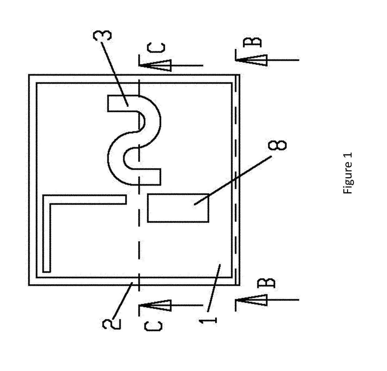
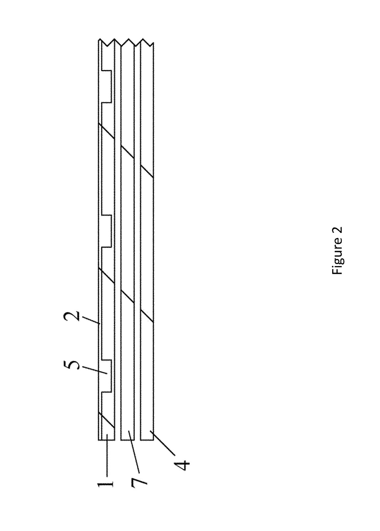
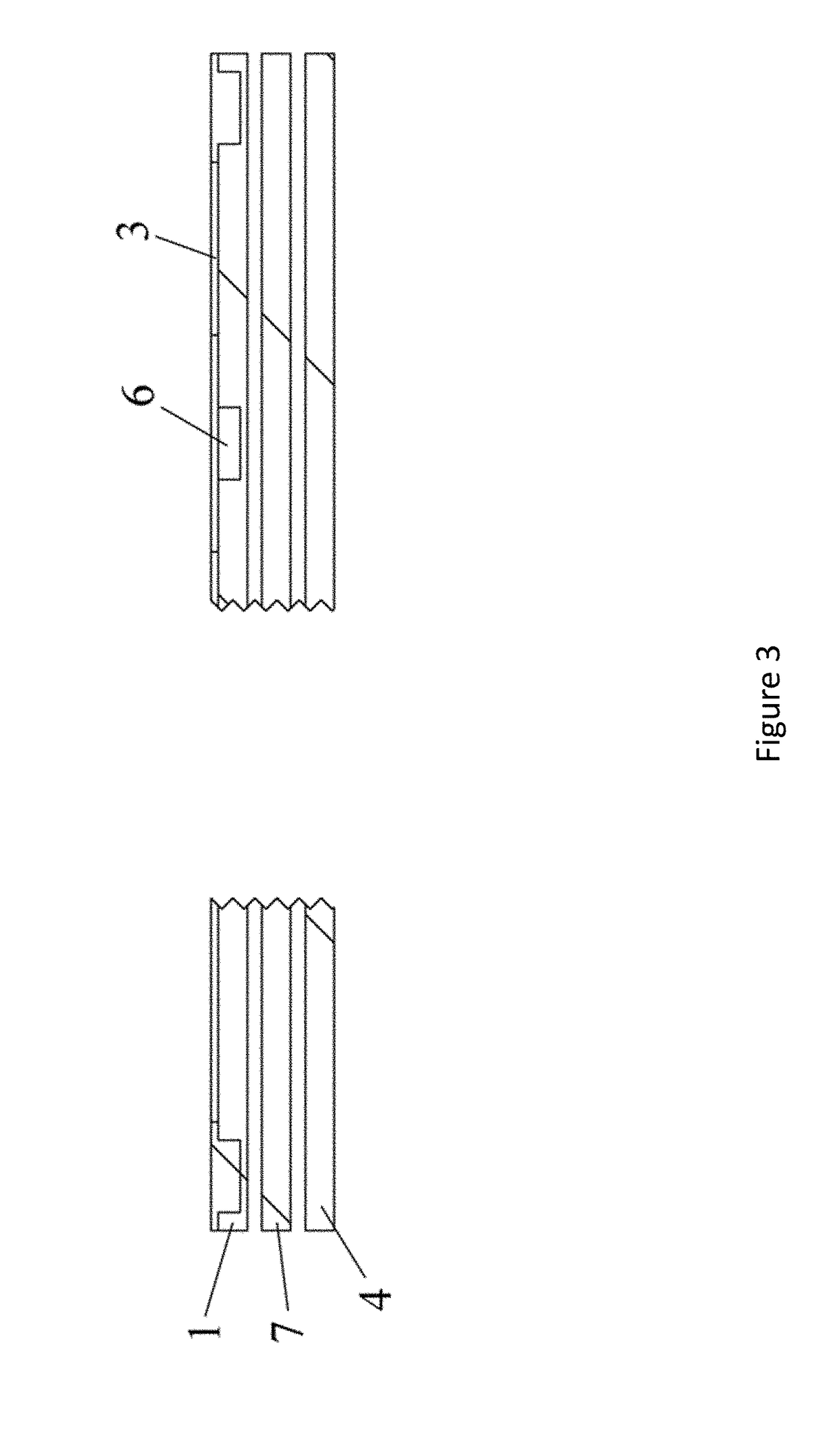
[0032]Aspects of embodiments of the present invention relate to a directional radar transmitting and receiving system that transmits and receives radar signals, reduces or avoids false triggering, and provides stability and adapts to different environments. In some embodiments, the directional radar transmitting and receiving system may include a sensor circuit board and a main control board. The sensor circuit board may include a non-conductive substrate integrated with a microwave oscillator, a transmitting antenna and a receiving antenna. The main control board may include a signal amplifying circuit, a main control chip and a switch circuit. The transmitting antenna transmits a high-frequency microwave signal, while the receiving antenna receives the frequency-shifted reflection of the transmitted microwave signal. A pulse wave signal is formed by applying frequency mixing and wave detection techniques to the frequency-shifted signal, and output to the signal amplifying circuit ...


PUM


Abstract

According to one embodiment of the present invention, a directional radar transmitting and receiving system includes: a main control chip is configured to determine whether a pulse wave signal output by a sensor circuit board meets a triggering condition wherein each of a plurality of evaluation processes is satisfied, the evaluation processes including: a first evaluation process including: determining whether a width and an amplitude of the pulse wave signal meets a threshold amplitude; and a second evaluation process including: comparing a shape of the pulse wave signal output by the sensor circuit board with a pre-stored default triggering signal shape; and determining that the second evaluation process is satisfied when the shape of the pulse wave signal matches the pre-stored default triggering signal shape.

Description

CROSS-REFERENCE TO RELATED APPLICATION(S)[0001]This application claims priority to Chinese Utility Model Patent Application No. 201721111845.3, filed on Sep. 1, 2017 in the State Intellectual Property Office of the People's Republic of China and Chinese Patent Application No. 201710875131.8, filed on Sep. 25, 2017 in the State Intellectual Property Office of the People's Republic of China, the entire disclosures of which are incorporated by reference herein.BACKGROUND OF THE INVENTION1. Field[0002]Aspects of embodiments of the present invention relate to systems and methods for controlling electrical appliances2. Related Art[0003]Conventional radar transmitting and receiving devices utilize non-directional or omnidirectional transmitting. However, conventional radar is susceptible to errors, such as false triggering and false operation, especially when using such conventional radar transmitting and receiving techniques are used to trigger a switch to control electrical appliances. F...

Claims


Application Information

Patent Timeline
Patent Type & Authority Applications(United States)
IPC IPC(8): G01S7/03H01Q1/24G01S13/56
CPCG01S7/032H01Q1/247G01S13/56H01Q1/38H01Q15/14
Inventor GAO, BOLIU, XIAO XIONG
Owner GARDENIA INDAL
Why Eureka
Try Eureka