Mini flat antenna system

a flat antenna and antenna body technology, applied in the direction of antennas, antenna details, electrical equipment, etc., can solve the problems of unfavorable orientation, unfavorable simple shrinking of the height (i.e., the diameter) of the coil, and the receiver will protrude rather far off the body, so as to achieve less energy, less energy, and more efficient energy transfer

Inactive Publication Date: 2014-09-18
SENSEONICS INC
View PDF16 Cites 31 Cited by
  • Summary
  • Abstract
  • Description
  • Claims
  • Application Information

AI Technical Summary

Benefits of technology

[0017]A thin flexible antenna embodying aspects of the invention may use a polymer / ferrite substrate. The curvature of a flexible antenna may allow more efficient energy transfer to a subcutaneous sensor. The more efficient energy transfer may require less energy (i.e., a smaller battery), which will in turn increase lifetime of a transceiver battery, allow longer time between recharges, and provide increased sensor reading range. An increased flexibility in material of the antenna may allow the transceiver and the antenna therein to be bent around an arm, wrist, ankle, leg, waist, or other body curvature and, thus, make the transceiver more conformal. Also, a flexible ferrite substrate may not break as easily as a ceramic ferrite substrate, and, as a result, a transceiver having an antenna with a flexible substrate may not need special protection for the antenna. There may be fewer limitations regarding shape and thickness of the antenna. Additionally, ferrite acts as a magnetic amplifier and, thus, may create a stronger signal.
[0018]In some embodiments, a flexible antenna may be embedded in an adjustable band, which may fit around an appendage (e.g., wrist, arm, ankle, or leg) or waist. The adjustable and flexible design may direct a majority of the electric field to a subcutaneous sensor allowing for better communication and providing more efficient power to the sensor.
[0019]In some embodiments, the transceiver may include an array of smaller antennas. The array configuration of antenna coils may allow for constant communication with a subcutaneous sensor even if the orientation of the sensor has changed within the body since implantation. In some embodiments, electronics within the transceiver may turn on and off the antennas in the antenna array, thus determining which antennas will operate for communication. This configuration may allow for reduced power consumption and / or may correct for altered sensor orientation.
[0020]In some embodiments, the transceiver antenna may include bent ends or be shaped as a “U” to focus the magnetic field in the direction of the sensor. Changing the shape of the antenna may allow for electric field focusing on an implanted sensor, thereby creating a more effective power transfer and increasing communication to the sensor.

Problems solved by technology

Unfortunately, a typical cylindrical coil is relatively thick, which means that the transceiver will protrude rather far off the body.
The transceiver coil is more efficient at transmitting energy if its cross-sectional area is larger, so it is not desirable to simply shrink the height (i.e., the diameter) of the coil.
This orientation is unfavorable from a physics perspective, but it is required because of the constraint of the orientation of the long axis of the sensor.
Also, a flexible antenna may be harder to break than a typical rigid antenna, such as an antenna with a ceramic ferrite substrate.
Over time, detuning can result in signals that drift outside the sensor's range, causing the antenna to perform below the specifications required to communicate and power the sensor.
Also, a flexible ferrite substrate may not break as easily as a ceramic ferrite substrate, and, as a result, a transceiver having an antenna with a flexible substrate may not need special protection for the antenna.

Method used


Image

  • Mini flat antenna system
  • Mini flat antenna system
  • Mini flat antenna system

Examples


Embodiment Construction

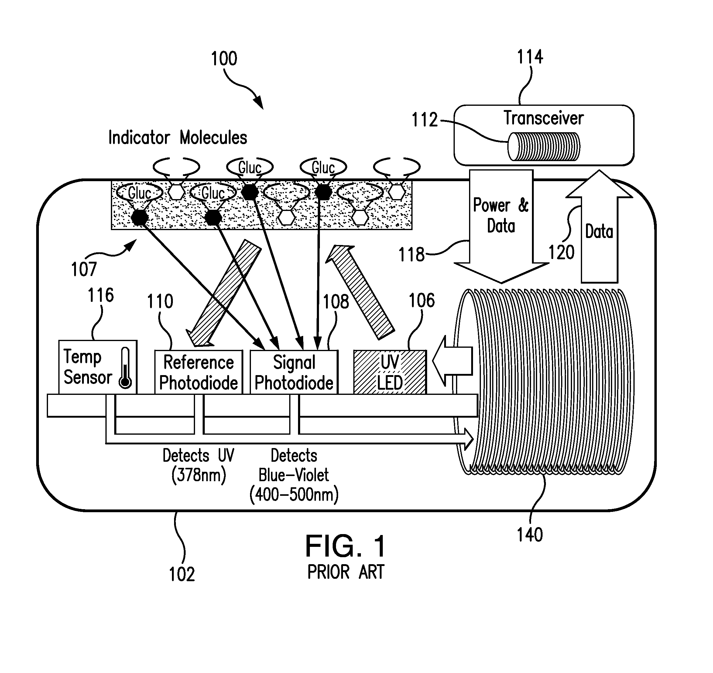
[0037]FIG. 1 is a schematic view of a sensor system 100, which includes an implantable sensor 102 and a sensor transceiver 114, known in the art. The implantable sensor 102 includes an antenna 140, a light source 106, indicator molecules 107, photodetectors 108, and a reference photodetector 110. The implantable sensor 102 receives power and data 118 from the transceiver 114 through the antenna 140, which may be, for example, a coil. The sensor antenna 140 may receive power from the transceiver antenna 112, e.g., through inductive coupling, as represented by the “power and data” arrow 118 and the data arrow 120. The power received by the sensor antenna 140 drives the light source 106, which may be, for example, a light emitting diode (LED) or, possibly, an ulta-violet light emitting diode. The light source 106 emits radiation, including radiation over a wavelength that interacts with the indicator molecules 107. The indicator molecules 107 may be fluorescent indicator molecules or a...


PUM


Abstract

A system for communicating with a subcutaneous sensor includes a transceiver with a flat antenna. The flat antenna may include a cross section in which the height and the width are not equal. The coils of the antenna may be mounted on a substrate, which may be flexible. The flexible substrate may allow the antenna to conform to the contours of body parts, such as arms, wrists, ankles, legs, or waists.

Description

CROSS-REFERENCE TO RELATED APPLICATIONS[0001]The present application claims the benefit of priority to U.S. Provisional Application Ser. No. 61 / 794,183, filed on Mar. 15, 2013, which is incorporated herein by reference in its entirety.BACKGROUND[0002]1. Field of the Invention[0003]The present invention relates generally to sensors for implantation within a living animal and detection of an analyte in a medium within the living animal and external transceivers for communicating with the sensors via antenna coils. The present invention also relates to external transceivers having an essentially flat antenna design.[0004]2. Discussion of the Background[0005]A sensor configured to detect an analyte, such as glucose, may be implanted, e.g., subcutaneously, in the body of a living animal, such as a human. The sensor may detect the analyte with florescent indicator molecules that emit an amount of light when irradiated with excitation light as disclosed in co-owned U.S. Pat. No. 7,822,450,...

Claims


Application Information

Patent Timeline
Patent Type & Authority Applications(United States)
IPC IPC(8): H01Q7/00
CPCH01Q7/00H01Q1/273H01Q7/06
Inventor TANKIEWICZ, SZYMON
Owner SENSEONICS INC
Why Eureka
Try Eureka