Shrinking process for producing solid, transportable and printable containers and a device for carrying out a shrinking process of this type

a technology of printable containers and shrinking processes, which is applied in the direction of packaging, containers with multiple articles, wrappers, etc., can solve the problems of uneven shrinking process of wrapping films and the possibility of reducing so as to reduce the energy output to the environment and facilitate the shrinking process. , the effect of rapid container shape stabilization

Active Publication Date: 2011-05-24
KHS GMBH
View PDF15 Cites 2 Cited by
  • Summary
  • Abstract
  • Description
  • Claims
  • Application Information

AI Technical Summary

Benefits of technology

[0010]With the new shrinking process it was possible to achieve an efficient energy transfer, wherein the heat-transfer coefficient between the media or substances involved, the type and size of the respectively heated surface and the flow velocity of the hot gas over the entire heat exchange or convection surface and the gas exchange with the environment was optimized. It was possible through certain measures to keep the core temperature low and to locally heat seal the packaging film by a narrow limitation of the high temperatures, wherein the individual objects (packaged goods) were heated to the necessary shrink temperature for a short time only at their surface. Furthermore, it was possible to reduce the energy output to the environment in that the hot air used to seal the film ends overlapping in the base area was directed only at the base area of the container in a locally limited manner. It was therefore possible to achieve a rapid shape stabilization of the container through the formation “in situ” of a peripheral shell, so that the articles were already fixed in their position relative to one another at the start of the shrinking process. The container already stabilized in the base area thus withstood even higher pressure stresses during lateral application of hot air, so that it was possible to restrict the blowing process to a short treatment duration.
[0011]At the same time the advantage resulted with continuous transport, in particular with containers with a large floor area, that it was possible to avoid a heat accumulation in the center floor area or an inadmissible heating of the articles to be packaged through the loaded hot air. There had hitherto been a danger of the side sections of the container being heated through the hot air streaming from all sides and influencing the shrinking process of the wrapping film unevenly. It was possible to solve this problem through a rapid continuous transport of the container on a reticular structure in combination with a local impingement of the base areas with hot air. Hot air is hereby introduced in bundles of discretely distributed gas jets into a convection zone, which is limited by the container base on the one hand and outlet air openings on the other hand. The hot air flowing in is deflected with deep interaction with the film on the container base and guided back to the gas circulation system with the reverse flow direction. This form of hot gas guidance is described below as a reverse flow. It is achieved through a parallel movement of convection zone and container base at different speeds that during the transport of the container the convection zone slowly moves with it over the entire base surface without causing a heat accumulation or irregular shrinking of the film at the container sides. Through the particular gas guidance in the form of a reverse flow, the heat transfer is carried out in a defined convection zone from the hot gas into the base area of the container. The local energy input can thereby be optimally adjusted to the material thickness or density of the film by control of the flow velocity of the hot gas and optimally adjusted over the exactly definable heat exchange or convection surface.

Problems solved by technology

Furthermore, it was possible to reduce the energy output to the environment in that the hot air used to seal the film ends overlapping in the base area was directed only at the base area of the container in a locally limited manner.
There had hitherto been a danger of the side sections of the container being heated through the hot air streaming from all sides and influencing the shrinking process of the wrapping film unevenly.

Method used


Image

  • Shrinking process for producing solid, transportable and printable containers and a device for carrying out a shrinking process of this type
  • Shrinking process for producing solid, transportable and printable containers and a device for carrying out a shrinking process of this type
  • Shrinking process for producing solid, transportable and printable containers and a device for carrying out a shrinking process of this type

Examples


Embodiment Construction

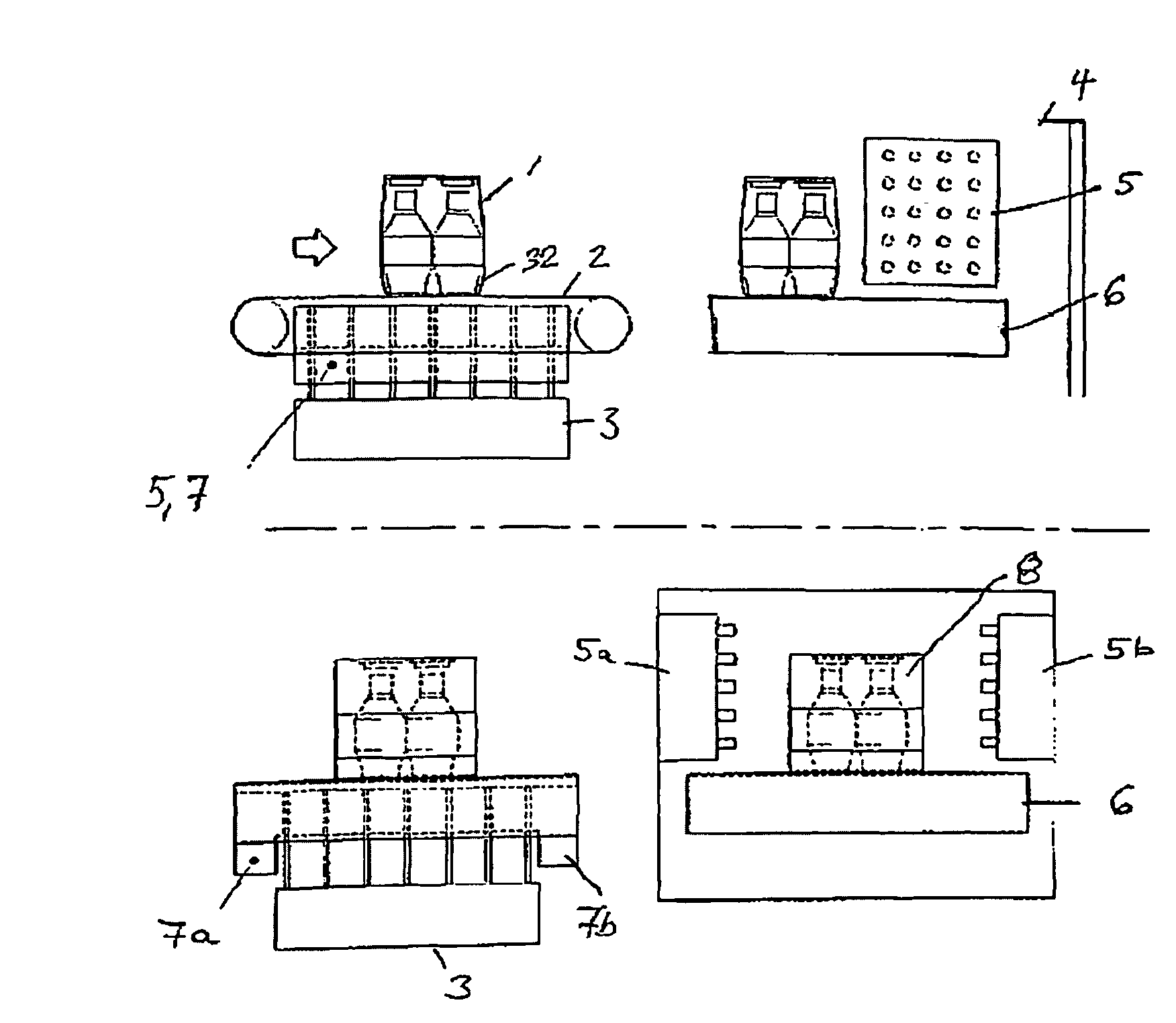
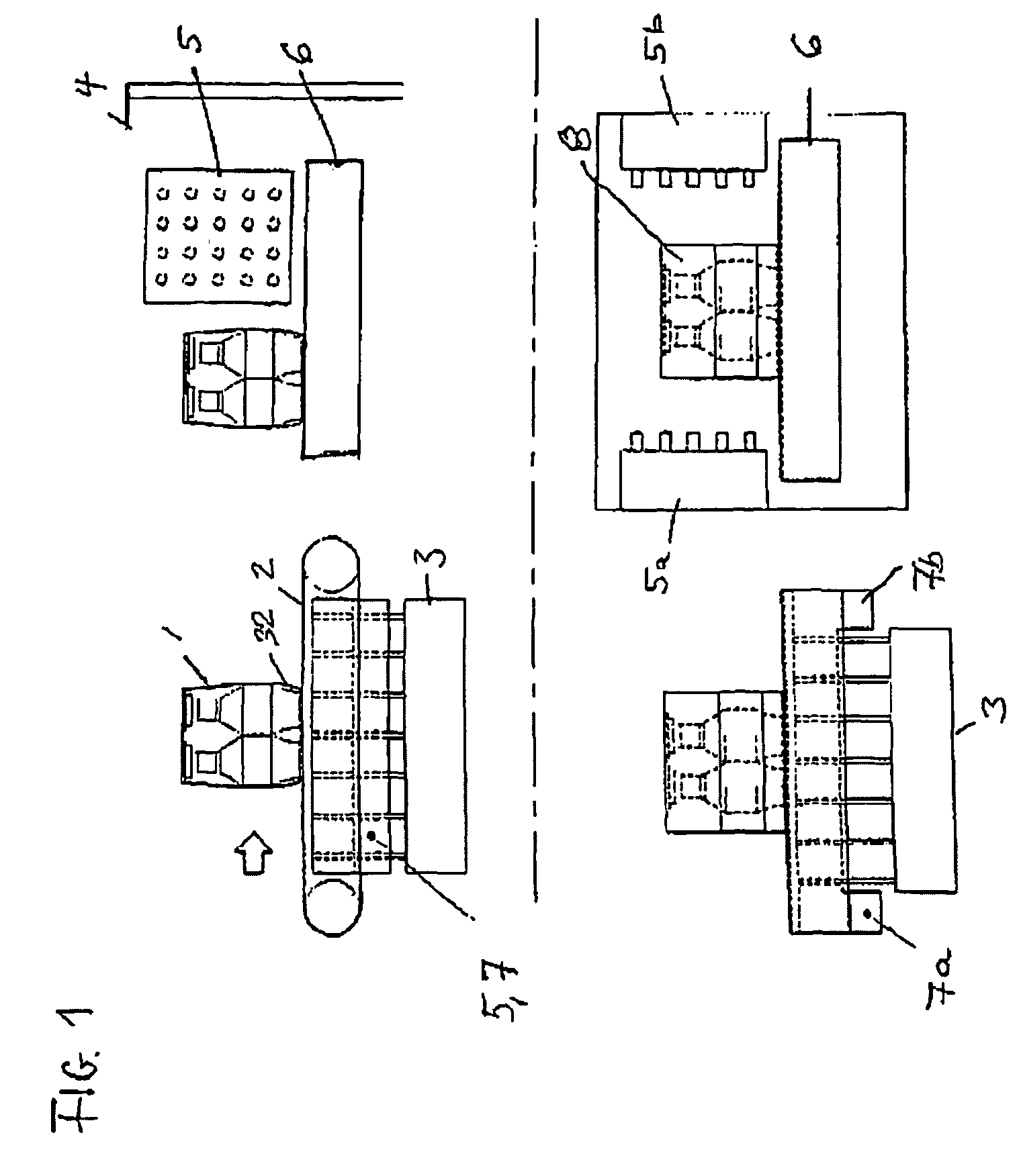
[0021]The upper portion of FIG. 1 shows the device according to the invention for carrying out a shrinking process in front view. The inlet air and outlet air system 5, 7 is discernible with the container 1, which is arranged on a conveyor belt 2 over a hot air source 3. The hot air applied in reverse flow (see arrow directions in FIG. 3) serves to form a pre-stabilizing peripheral shell 32 in the base area of the container.

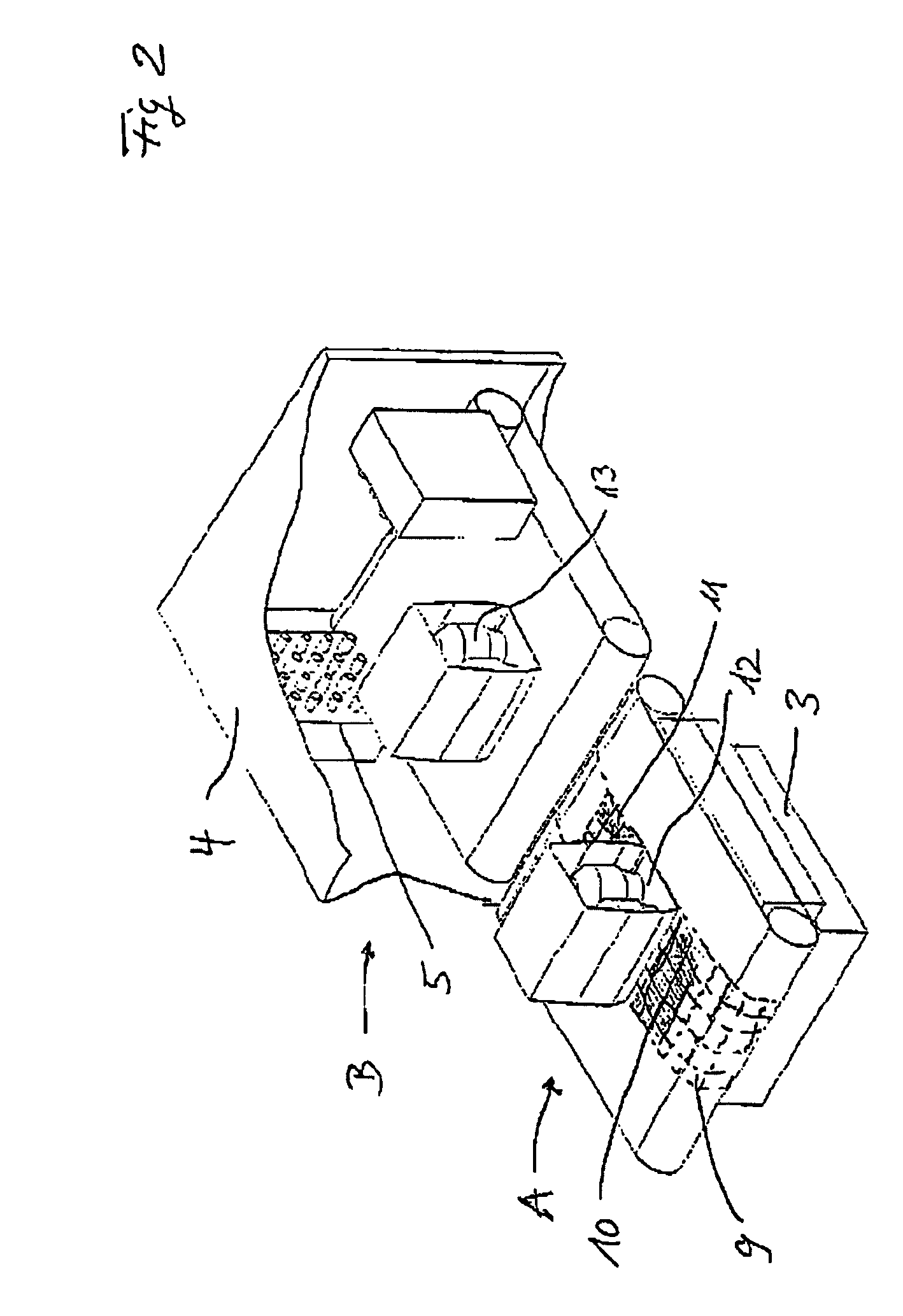
[0022]In the right portion of FIG. 1 the container 1 is shown in a machine that has a lateral hot air supply. The articles (bottles) of the container are conveyed via a transport belt 6 in the product travel direction through the shrink wrapping machine 4. As soon as the container 1 with the wrapping film8 arrives in front of the hot air supply 5 there is a danger that the film wrapping will be inflated by the air pressure and will be in danger of slipping thereby. This is prevented by the peripheral shell formed in advance in the area of the container base, whic...


PUM

PropertyMeasurementUnit
flow speedsaaaaaaaaaa
heat-sensitiveaaaaaaaaaa
areaaaaaaaaaaa

Abstract

The invention relates to a shrinking process for producing solid, transportable and printable containers by wrapping the articles to be packaged with a film in such a manner as to produce an overlapping section of the film ends on the base area, heating by heat exchange or convection in order to seal the free ends in the area of overlap, and finally heating in a shrinking oven, the container so produced being stabilized by the shrinking process. The method comprises first locally limiting the incoming hot air to the base area of the container to form a peripheral shell in the area of the bottle bottoms, the shape of the container being stabilized thereby, while the container is continuously transported during stabilization and the hot air directed onto the base area of the container in a bundle of discretely distributed gas jets is thereby discharged and guided back after a locally limited heat transfer with the film, and more hot gas is directed laterally against the continuously transported container at an increased lateral blow speed in order to complete the shrinking process. The invention further relates to a device for carrying out the shrinking process.

Description

CROSS-REFERENCE TO PRIOR APPLICATION[0001]This is a U.S. National Phase application under 35 U.S.C. §371 of International Application PCT / DE06 / 000870, filed May 19, 2006, and claims benefit of German Patent Application No. 10 2005 059 295.3, filed Dec. 9, 2005, both of which are incorporated herein. The International Application was published in German on Jun. 14, 2007 as WO 2007 / 065385.BACKGROUND OF THE INVENTION[0002]The invention relates to a shrinking process for producing solid, transportable and printable containers, in particular bottle containers with a height / width ratio of >1.FIELD OF THE INVENTION[0003]Shrinking processes for producing solid, transportable and printable containers are carried out nowadays in many forms with film packages that are used as a sales unit of bottles. The film is hereby also used as an advertising medium, e.g., for beverage bottles that are wrapped with a shrink film. Usually hot gases are used to heat the shrink films, in which gases the th...

Claims


Application Information

Patent Timeline
Patent Type & Authority Patents(United States)
IPC IPC(8): B65B53/02
CPCB65B53/063B65B2220/24B65B63/08B65D71/08
Inventor JUSTEN, HEINRICHDUMON, MARKUSMISZEWSKI, ANDREJANSEN, KURT
Owner KHS GMBH
Why Eureka
Try Eureka