Mounting structure of auxiliary member and vehicle seat with auxiliary member

a technology of auxiliary members and mounting structures, which is applied in the direction of seats, movable seats, and wheelchairs/auxiliary members that may interfere with each other, and achieve excellent effects, excellent effect, and excellent

Active Publication Date: 2022-03-08
TOYOTA JIDOSHA KK +1
View PDF11 Cites 0 Cited by
  • Summary
  • Abstract
  • Description
  • Claims
  • Application Information

AI Technical Summary

Benefits of technology

[0006]In view of the above, the present disclosure provides a mounting structure of an auxiliary member and a vehicle seat with an auxiliary member that are capable of suppressing interference between the auxiliary member and the wheelchair when the wheelchair is moved or turned back in the vehicle interior.
[0054]The vehicle seat of the at least one aspect has an excellent effect whereby, when the wheelchair is moved or turned back in the vehicle cabin, interference between the auxiliary member and the wheelchair can be avoided or reduced.

Problems solved by technology

However, if attachment portions of auxiliary members such as handrails are provided on both outer sides in the vehicle width direction of the floor panel, the space in the vehicle width direction at the vehicle interior becomes more narrow, so that when the passenger in the wheelchair moves or turns around in the wheelchair in the vehicle interior, the wheelchair and the auxiliary members may interfere with each other.
Further, “restriction of rotation” means that in an auxiliary member that is rotatable about a shaft extending along the seat width direction, rotation in at least one direction along the seat front-rear direction from the reference position is restricted.

Method used


Image

  • Mounting structure of auxiliary member and vehicle seat with auxiliary member
  • Mounting structure of auxiliary member and vehicle seat with auxiliary member
  • Mounting structure of auxiliary member and vehicle seat with auxiliary member

Examples


first exemplary embodiment

(Configuration of Handrail Member)

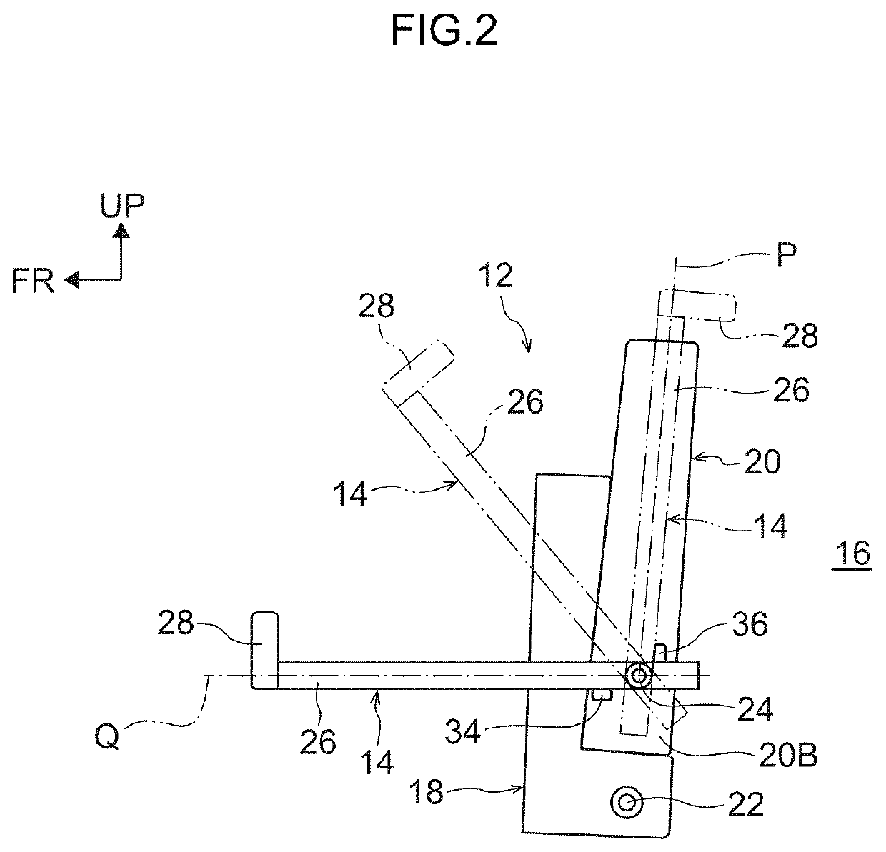
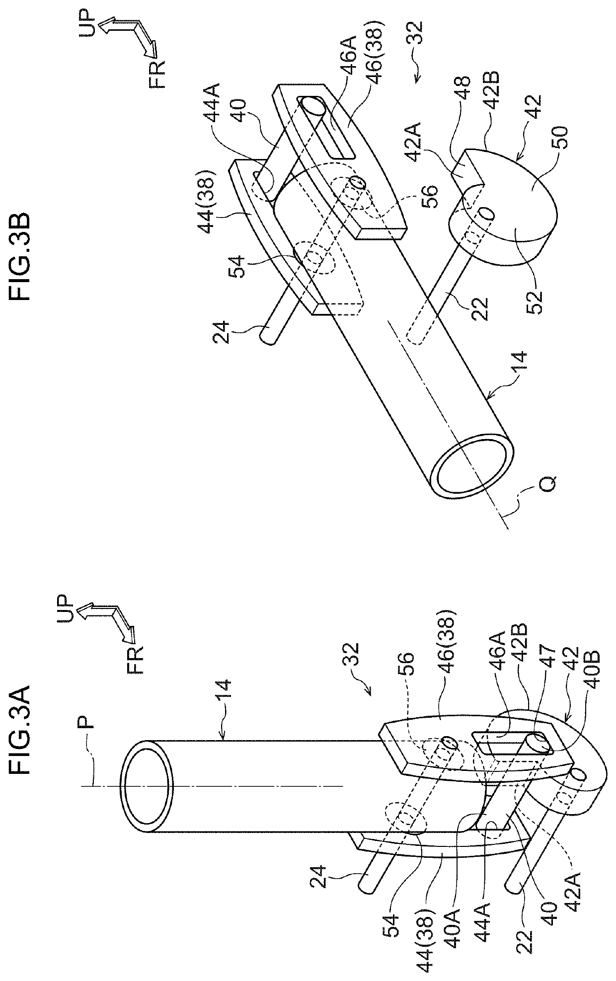
[0088]First, referring to FIGS. 1 to 11B, the configuration of the handrail member 14 according to the first embodiment of the present invention, that is, a seat body 12 of a vehicle seat to which an auxiliary member mounting structure 10 is attached, and an auxiliary member provided thereon, will be described.

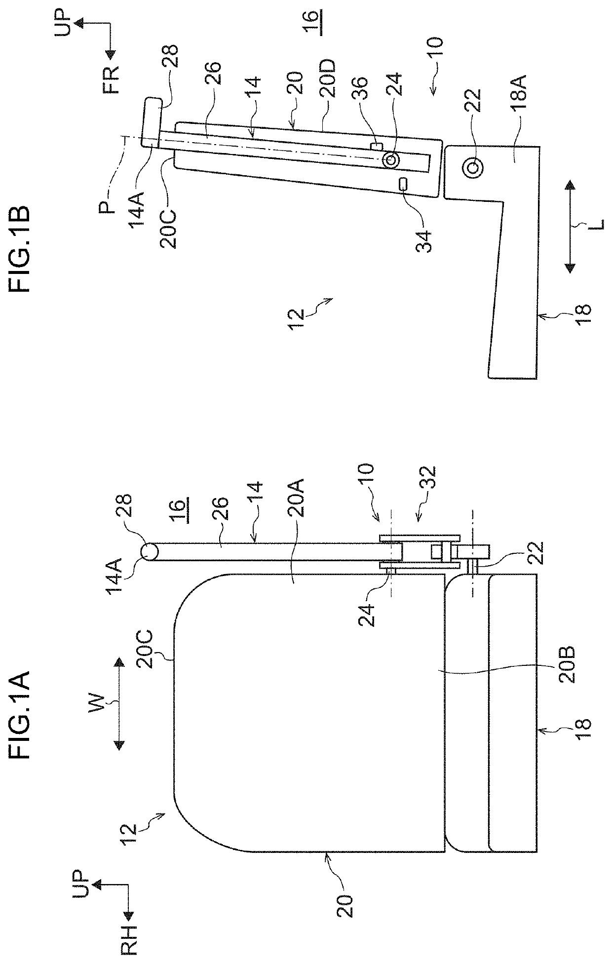
[0089]FIG. 1A shows a front view of a vehicle seat 12 including a handrail member 14 as an auxiliary member according to the first embodiment, and FIG. 1B shows a side view of the vehicle seat 12. As shown in FIGS. 1A and 1B, the vehicle seat 12 includes a seat cushion 18 on which an occupant in a vehicle cabin 16 can be seated, and a seat back 20 for supporting the back of the seated occupant.

[0090]At the rear end 18A of the seat cushion 18 of the vehicle seat 12 in the front-rear direction (arrow L direction), a shaft portion 22 is extends in the seat width direction (arrow W direction), and the seat cushion 18 is rotatable about the shaft p...

second exemplary embodiment

(Configuration of Table Member)

[0149]Next, with reference to FIGS. 12 to 16, the configuration of a table member 64 according to a second embodiment of the present invention, that is, of a vehicle seat (seat main body) 62 to which an auxiliary member mounting structure 60 is applied and the table member (auxiliary member) 64 thereon, will be described. Hereinafter, substantially the same components as those of the first embodiment are denoted by the same reference numerals, and description thereof will be omitted.

[0150]FIGS. 12A and 12B are each side views of a vehicle seat 62 to which is attached a table member 64 as an auxiliary member according to the second embodiment. FIG. 12A shows a seating position of the seat cushion 18 and a reference state (reference position P) of the table member 64, and FIG. 12B shows a storage position of the seat cushion 18 and a holding state (holding position R) of the table member 64.

[0151]In this embodiment, as shown in FIG. 12B, the table member...


PUM


Abstract

An auxiliary member attachment structure for a vehicle seat. The auxiliary member attachment structure includes an auxiliary member at an outer side of the vehicle seat. The vehicle seat has a seat cushion that is capable of transitioning from a seating position to a storage position aligned with a seat back. The auxiliary member being rotatable, about a shaft in the vehicle seat extending along the seat width direction, between a reference position at which the auxiliary member is upright and a holding position at which the auxiliary member is rotated closer to a front side of a vehicle. The auxiliary member attachment structure further includes a rotation restriction unit configured to restrict rotation of the auxiliary member at the reference position when the seat cushion is at the seating position, and cease the restriction of rotation of the auxiliary member when the seat cushion is at the storage position.

Description

CROSS-REFERENCE TO RELATED APPLICATION[0001]This application claims priority under 35 USC 119 from Japanese Patent Application No. 2019-167139 filed Sep. 13, 2019, the disclosure of which is incorporated by reference herein in its entirety.BACKGROUNDTechnical Field[0002]The present disclosure relates to a mounting structure of an auxiliary member and a vehicle seat with the auxiliary member.Related Art[0003]Japanese Patent Application Laid-Open No. 2015-80658 discloses a technique whereby, in a handrail attached to a vehicle in order to be gripped by the occupant of a wheelchair carried in a vehicle for a handicapped person, an elastic body is jointly fastened to a fastening portion of the handrail and rattling of the handrail is suppressed.[0004]In the above technology, a recess is formed on both sides in a vehicle width direction of a floor panel in a vehicle interior, a pair of legs connected to a seat cushion of a vehicle seat are attached in the recesses, and the seat cushion i...

Claims


Application Information

Patent Timeline
Patent Type & Authority Patents(United States)
IPC IPC(8): B60N2/30B60N2/02B60N2/75B60N2/24
CPCB60N2/3045B60N2/0224B60N2/245B60N2/767B60N2/79B60N3/026B60N2/3047B60N3/004B60N2/305B60N2/242B60N3/02B60N2002/948B61D33/0007
Inventor OGAWA, TAKASHINONOYAMA, SATOSHI
Owner TOYOTA JIDOSHA KK
Why Eureka
Try Eureka