Automatic voltage switching circuit for selecting a higher voltage of multiple supply voltages to provide as an output voltage

a voltage switching circuit and output voltage technology, applied in the direction of pulse manipulation, power consumption reduction, pulse technique, etc., can solve the problems of voltage fluctuations of power supplies such as logic and memory power supplies described above, and achieve the effects of reducing or avoiding forward biasing, reducing or avoiding interference of output voltage, and reducing or avoiding interferen

Inactive Publication Date: 2018-05-01
QUALCOMM INC
View PDF10 Cites 0 Cited by
  • Summary
  • Abstract
  • Description
  • Claims
  • Application Information

AI Technical Summary

Benefits of technology

[0006]Aspects disclosed in the detailed description include an automatic voltage switching circuit for selecting a higher voltage of multiple supply voltages to provide as an output voltage. For example, certain applications may be designed to operate based on receiving an output voltage that is the higher voltage among multiple supply voltages even in light of the multiple supply voltages fluctuating over time. In this regard, in one example, an automatic voltage switching circuit is provided that is configured receive a first and second supply voltage as input voltages from respective power supplies. The automatic voltage switching circuit is configured to generate a compare signal indicating which of the first supply voltage and the second supply voltage is the higher voltage. The automatic voltage switching circuit then generates a select indicator indicative of whether the first or second supply voltage is the higher voltage. The select indicator controls activation of tr...

Problems solved by technology

However, voltages provided by power supplies, such as the logi...

Method used


Image

  • Automatic voltage switching circuit for selecting a higher voltage of multiple supply voltages to provide as an output voltage
  • Automatic voltage switching circuit for selecting a higher voltage of multiple supply voltages to provide as an output voltage
  • Automatic voltage switching circuit for selecting a higher voltage of multiple supply voltages to provide as an output voltage

Examples


Embodiment Construction

[0018]With reference now to the drawing figures, several exemplary aspects of the present disclosure are described. The word “exemplary” is used herein to mean “serving as an example, instance, or illustration.” Any aspect described herein as “exemplary” is not necessarily to be construed as preferred or advantageous over other aspects.

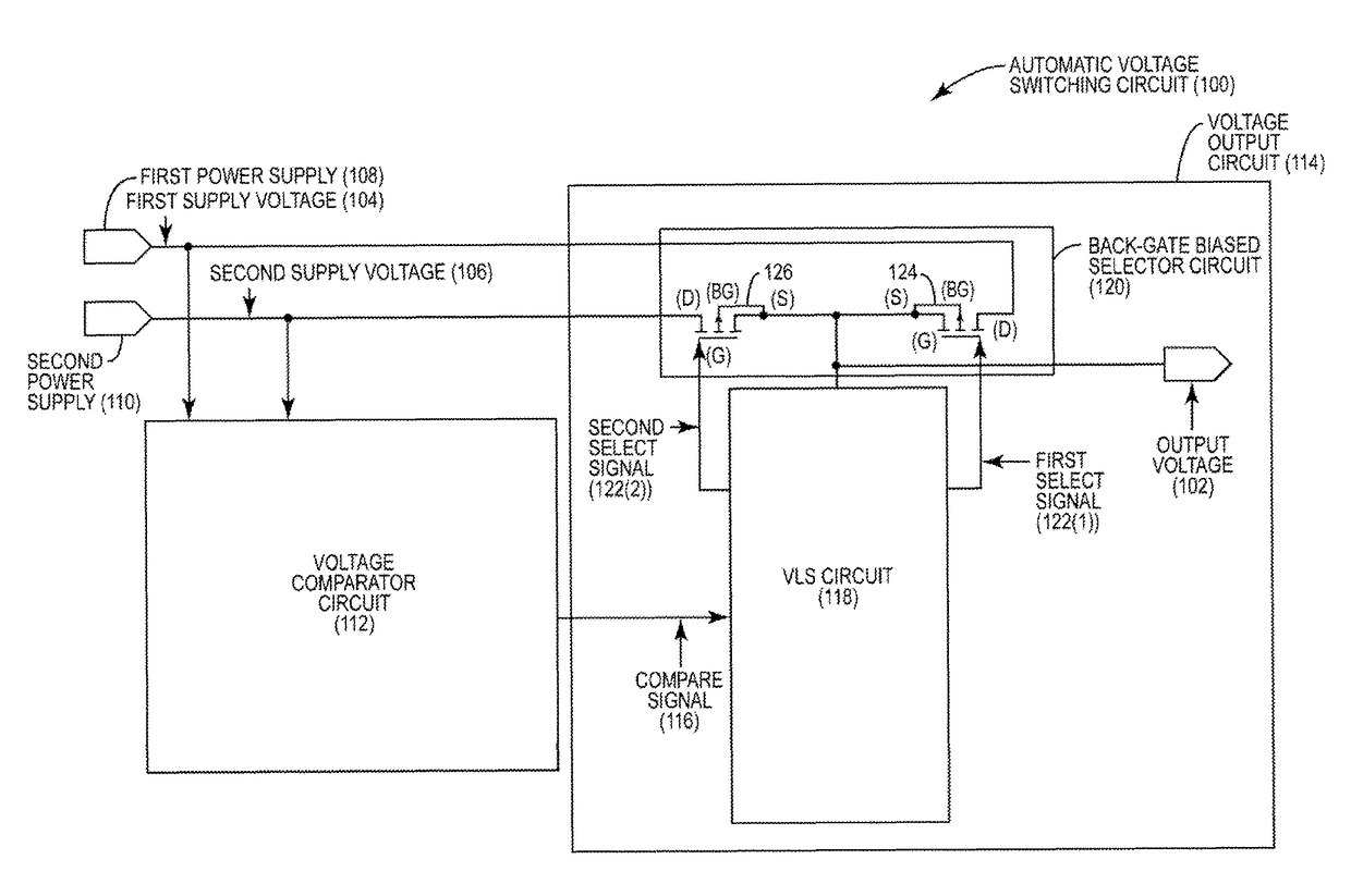
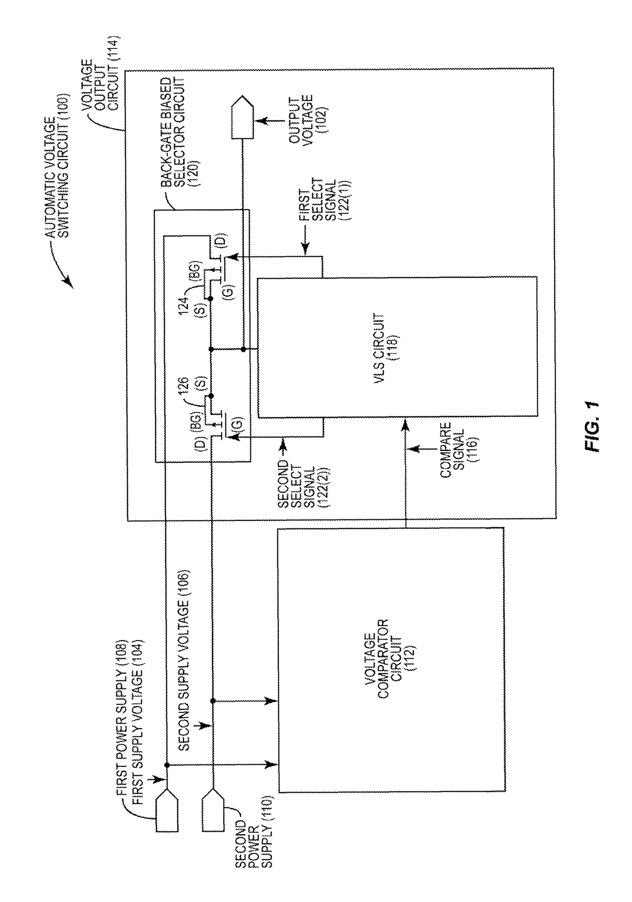
[0019]FIG. 1 illustrates an exemplary automatic voltage switching circuit 100 that is configured to provide an output voltage 102 that is a higher voltage between a first supply voltage 104 and a second supply voltage 106. In this example, the first supply voltage 104 is provided by a first power supply 108, while the second supply voltage 106 is provided by a second power supply 110. The automatic voltage switching circuit 100 includes a voltage comparator circuit 112 and a voltage output circuit 114. The voltage comparator circuit 112 is configured to generate a compare signal 116 indicating which of the first supply voltage 104 and the second suppl...


PUM


Abstract

Automatic voltage switching circuits for providing a higher voltage of multiple supply voltages are disclosed. In one aspect, an automatic voltage switching circuit is configured to generate a compare signal indicating which of a first supply voltage and a second supply voltage is a higher voltage. The automatic voltage switching circuit is further configured to generate first and second select signals based on the compare signal, wherein the first and second select signals are in a voltage domain of the higher voltage. Transistors corresponding to the first and second supply voltages control switching the output voltage to the higher voltage in response to the first and second select signals. Biasing the back-gates of the transistors using the output voltage reduces or avoids forward biasing in the body diodes of the transistors, thus reducing the possibility of the output voltage causing interference on a power supply corresponding to a non-activated transistor.

Description

PRIORITY CLAIM[0001]The present application claims priority under 35 U.S.C. § 119(e) to U.S. Provisional Patent Application Ser. No. 62 / 147,722 filed on Apr. 15, 2015 and entitled “AUTOMATIC VOLTAGE SWITCHING CIRCUITS FOR SELECTING AND PROVIDING A HIGHER VOLTAGE PARTICULARLY SUITED FOR BIASING TRANSISTOR BACK-GATES,” the contents of which is incorporated herein by reference in its entirety.BACKGROUNDI. Field of the Disclosure[0002]The technology of the disclosure relates generally to providing power from a power source to an electrical component for powering their operation, and more particularly to voltage switching circuits for providing power from one or multiple power sources to electronic components for powering their operation.II. Background[0003]Circuits are increasingly being designed with multiple operating voltage domains (“voltage domains”). In this manner, circuit paths are provided which pass through the multiple voltage domains to provide different operating voltages t...

Claims


Application Information

Patent Timeline
IPC IPC(8): H02J1/00H02J1/10H03K5/24H03K19/003H03K19/00
CPCH02J1/10H03K19/00315H03K5/2481H03K19/0016
Inventor PRICE, BURT LEEKOLLA, YESHWANT NAGARAJNATEKAR, NEEL SHASHANK
Owner QUALCOMM INC
Why Eureka
Try Eureka