

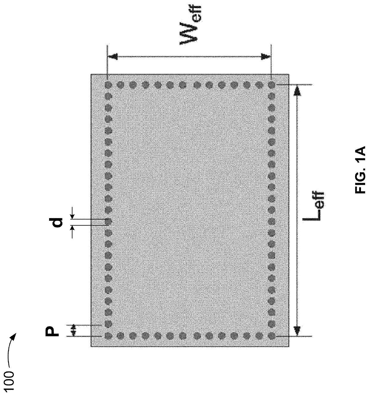
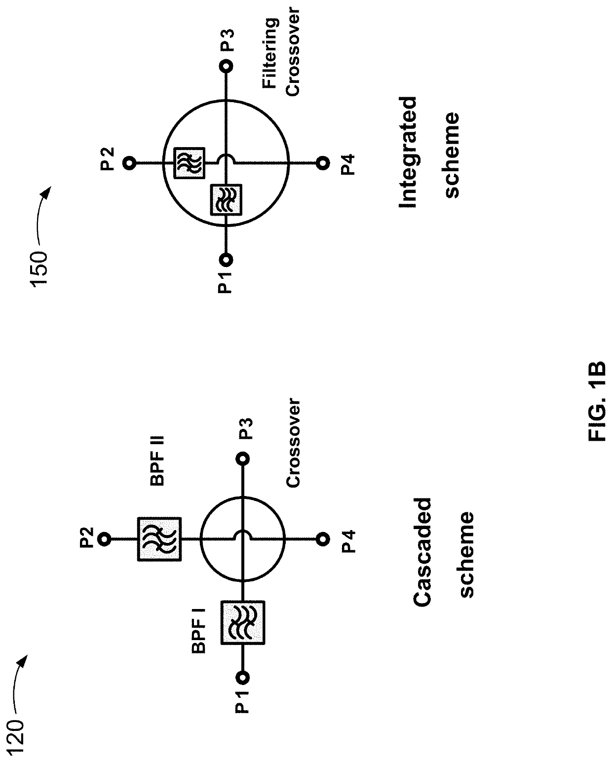
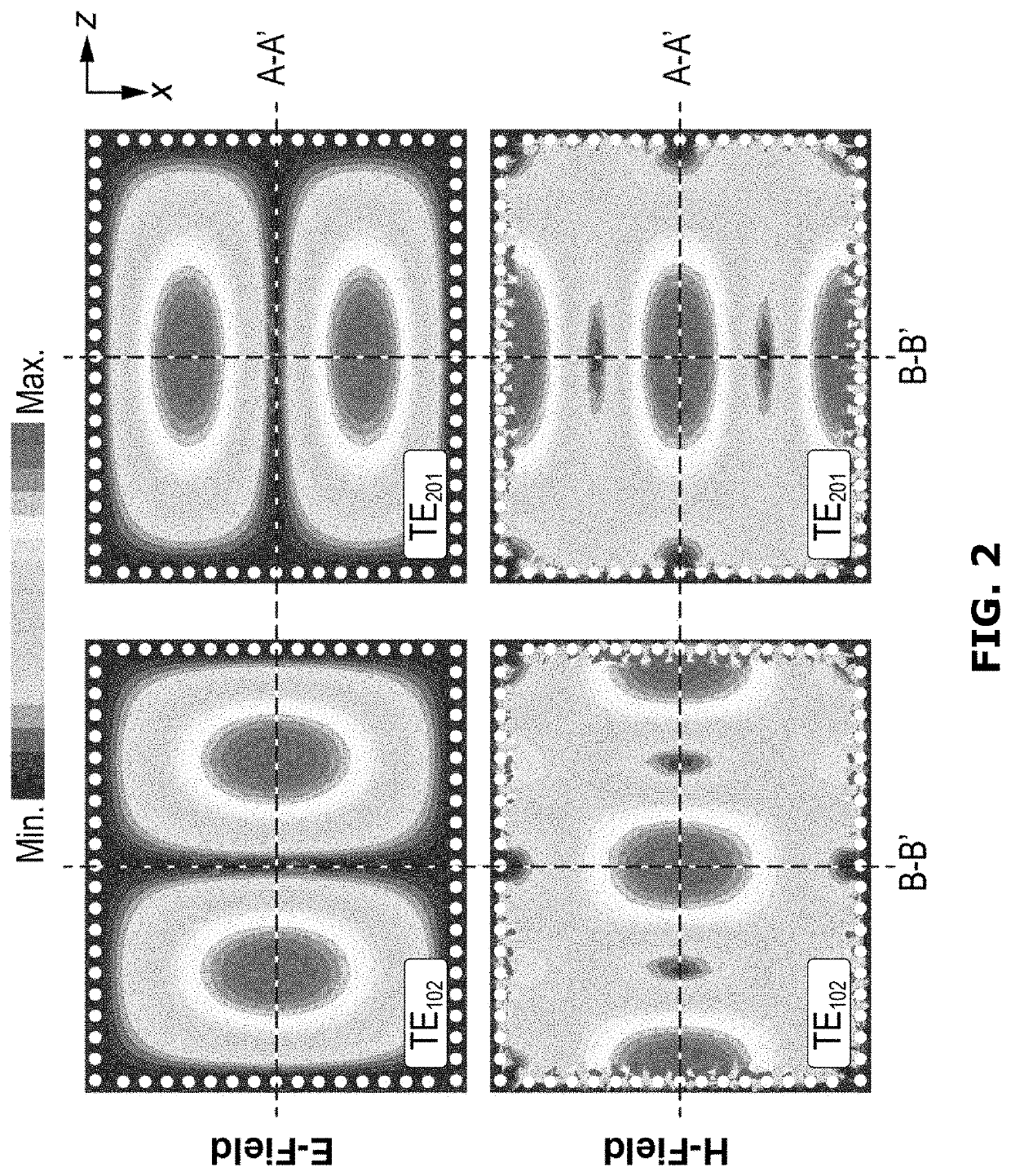
Substrate-integrated waveguide filtering crossover having a dual mode rectangular cavity coupled to eight single mode square cavities
a filter crossover and substrate-integrated waveguide technology, which is applied in the direction of waveguides, basic electric elements, waveguide type devices, etc., can solve the problems of increasing channel insertion loss (ils), design complexity, and inability to easily control the bws of these schemes without filtering functions integrated
- Summary
- Abstract
- Description
- Claims
- Application Information
AI Technical Summary
Benefits of technology
Problems solved by technology
Method used
Image

Examples
Embodiment Construction
[0074]Throughout this disclosure, the term “coupled” may mean directly or indirectly connected, electrically coupled, or operably connected; the term “connection” may mean any operable connection, including direct or indirect connection. In addition, the phrase “coupled with” is defined to mean directly connected to or indirectly connected through one or more intermediate components. Such intermediate components may include both or either of hardware and software-based components.
[0075]Further, a communication interface may include any operable connection. An operable connection may be one in which signals, physical communications, and / or logical communications may be sent and / or received. An operable connection may include a physical interface, an electrical interface, and / or a data interface.
[0076]In some example embodiments described in this disclosure, the footprints of SIW filtering crossovers are reduced, resulting in compact and highly integrated SIW filtering crossover devic...
PUM
| Property | Measurement | Unit |
|---|---|---|
| relative permittivity | aaaaa | aaaaa |
| relative dielectric constant εr | aaaaa | aaaaa |
| frequency | aaaaa | aaaaa |
Abstract
Description
Claims
Application Information