Directional radar transmitting and receiving sensor board

a sensor board and directional radar technology, applied in the direction of instruments, resonant antennas, reradiation, etc., can solve the problems of insufficient robustness of comparative directional radar transmitting and receiving devices when transmitting and receiving signals, easy to be easily damaged, and susceptible to errors in conventional radar, etc., to avoid or reduce interference

Active Publication Date: 2020-12-08
GARDENIA INDAL
View PDF14 Cites 0 Cited by
  • Summary
  • Abstract
  • Description
  • Claims
  • Application Information

AI Technical Summary

Benefits of technology

[0003]Aspects of embodiments of the present invention relate to a directional radar transmitting and receiving sensor board that is robust in transmitting and receiving signals, covering a wide area while avoiding or reducing interference.

Problems solved by technology

However, conventional radar is susceptible to errors, such as false triggering and false operation, especially when using such conventional radar transmitting and receiving techniques are used to trigger a switch to control electrical appliances.
Additionally, comparative directional radar transmitting and receiving devices are not sufficiently robust when transmitting and receiving signals.
Thus, the use of the comparative available switch controls that utilize directional radar transmitting and receiving is limited due to these technical issues.

Method used


Image

  • Directional radar transmitting and receiving sensor board
  • Directional radar transmitting and receiving sensor board
  • Directional radar transmitting and receiving sensor board

Examples


Embodiment Construction

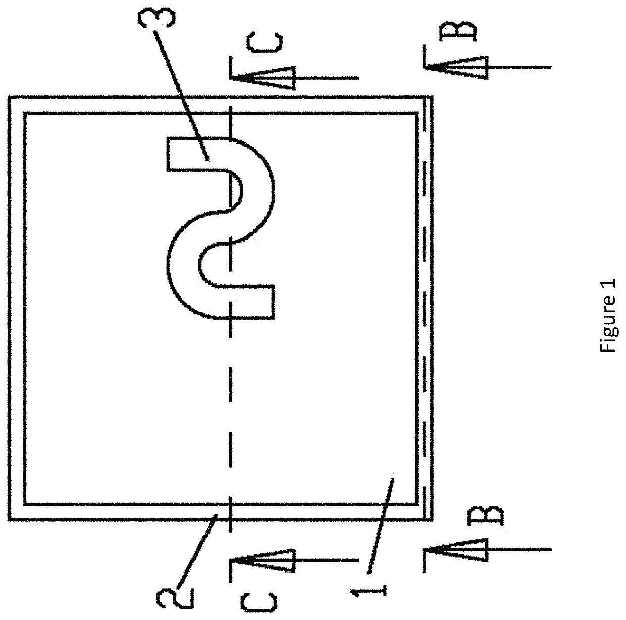
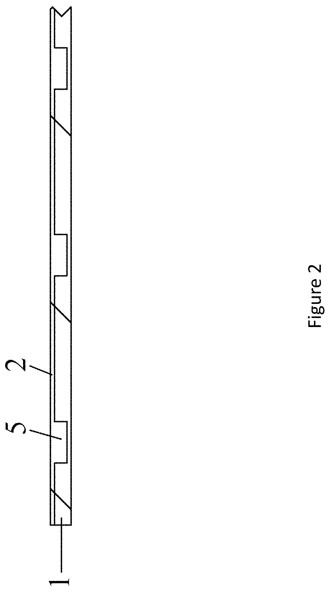
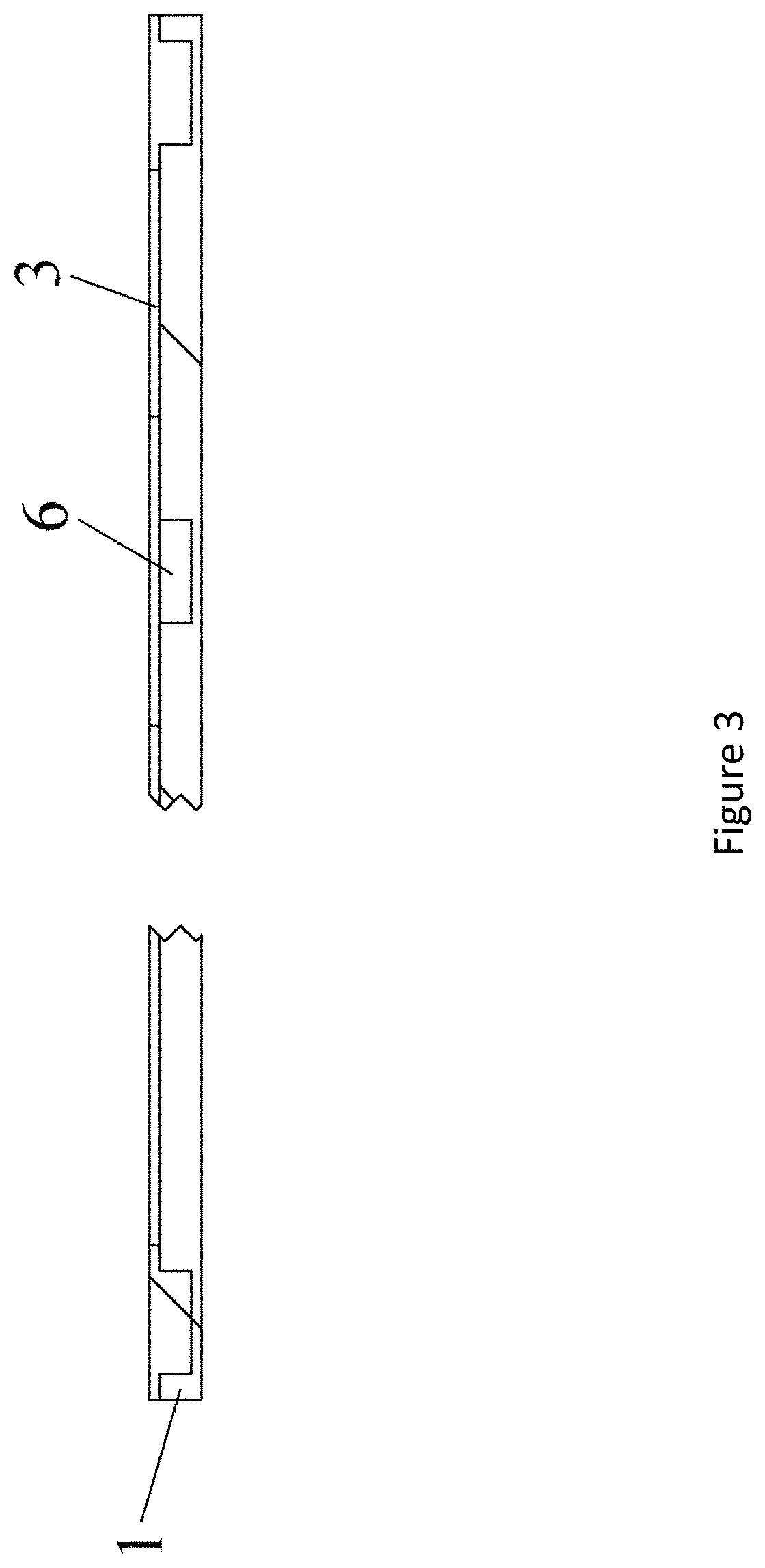
[0019]Aspects of embodiments of the present invention relate to a directional radar transmitting and receiving sensor board that transmits and receives radar signals, reduces or avoids false triggering, and provides stability and adapts to different environments. In some embodiments, the sensor board includes a non-conductive substrate integrated with a microwave oscillator. The microwave oscillator may include a RC oscillator circuit, a transistor, a first filter circuit configured to receive input signals, a second filter circuit configured to receive output signals, and a receiving antenna.

[0020]In some embodiments, the RC oscillator circuit may include a plurality of capacitors that are connected in parallel and connected to a transmitting antenna. In some aspects, one end of the capacitors is connected to ground while the other end is connected to the input power and the transmitting antenna. In some embodiments, the transmitting antenna is connected to the transistor at its co...


PUM


Abstract

A sensor board for transmitting and receiving directional radar signals including a non-conductive substrate having a plurality of first recesses distributed at intervals along at least one edge of the non-conductive substrate; a microwave oscillator including an RC oscillator circuit and a transistor Q1; an anti-coupling foil; a first filter circuit configured to filter an input power Vcc; a second filter circuit configured to filter an output signal; a receiving antenna; and a transmitting antenna including a first wire laid over the plurality of first recesses along the edge of the non-conductive substrate; and a plurality of first electrically conductive protrusions embedded in the first recesses, the first wire electrically connecting the first electrically conductive protrusions.

Description

CROSS-REFERENCE TO RELATED APPLICATION(S)[0001]This application claims priority of Chinese Utility Model Patent Application No. 201721150101.2, filed on Sep. 8, 2017 in the State Intellectual Property Office of the People's Republic of China, the disclosure of which is hereby incorporated by reference in its entirety.BACKGROUND OF THE INVENTION[0002]Conventional radar transmitting and receiving utilizes non-directional or omnidirectional transmitting. However, conventional radar is susceptible to errors, such as false triggering and false operation, especially when using such conventional radar transmitting and receiving techniques are used to trigger a switch to control electrical appliances. For example, in the context of controlling lights, two adjacent rooms that were both equipped with switches that utilize non-directional or omnidirectional radar transmitting often both light up when someone enters just one of the rooms. This is because when the radar detector in one room sens...

Claims


Application Information

Patent Timeline
Patent Type & Authority Patents(United States)
IPC IPC(8): G01S7/03G01S13/04H01Q1/52H01Q1/22G01S7/02
CPCG01S13/04G01S7/032H01Q1/525H01Q1/2283G01S7/023H01Q9/04
Inventor LIU, XIAO XIONG
Owner GARDENIA INDAL
Why Eureka
Try Eureka