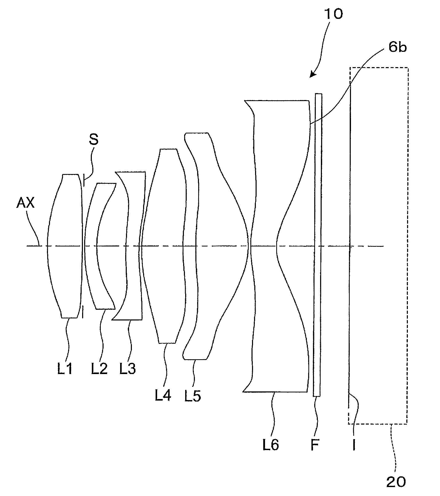
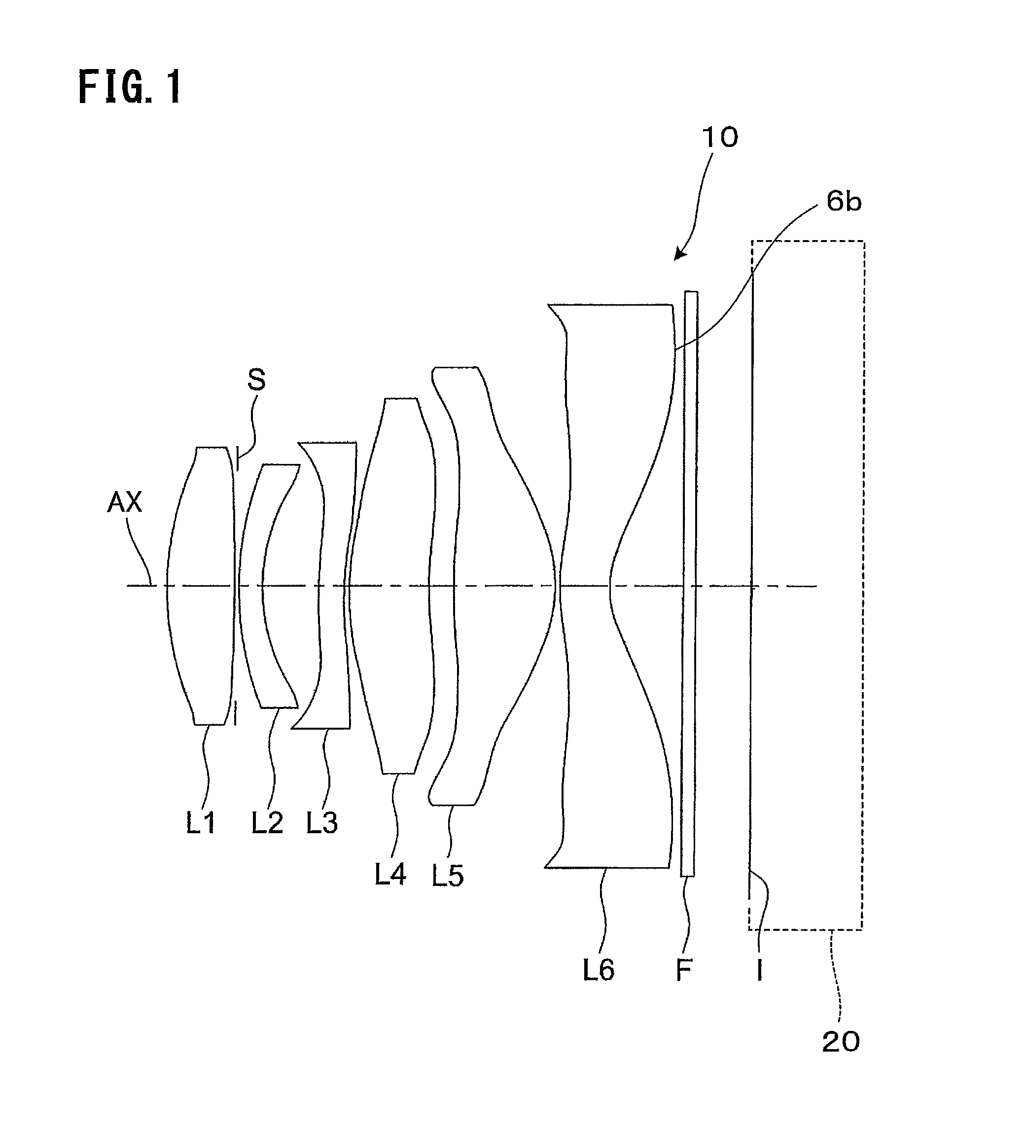
Image pickup lens

a pickup lens and image technology, applied in the field of small and fast image pickup lenses, can solve the problems of insufficient high performance that cannot be realized by a conventionally used f-number, and achieve the effect of small size, favorable correction, and reduced total length of image pickup lenses

Active Publication Date: 2014-07-22
KONICA MINOLTA OPTO
View PDF10 Cites 7 Cited by
  • Summary
  • Abstract
  • Description
  • Claims
  • Application Information

AI Technical Summary

Benefits of technology

[0058]Recently, for the purpose of downsizing the whole solid-state image pickup device, there has been developed a solid-state image sensor having a smaller pixel pitch and resultantly having a smaller image pickup surface size even if solid-state image sensors have the same number of pixels. An image pickup lens for such a solid-state image sensor having a smaller image pickup surface size is required to comparatively shorten the focal length of the entire system, and thus the curvature radius and the outer diameter of each lens become considerably small. Accordingly, as compared with a glass lens which is manufactured by time-consuming polishing processing, by configuring all the lenses with plastic lenses manufactured by injection molding, mass production is possible at a low cost even for a lens having a small curvature radius and outer diameter. Moreover, since press temperature of the plastic lens can be lowered, wear damage of an injection mold can be suppressed, and resultantly the number of injection mold exchanges and the number of maintenances can be reduced and it leads to cost reduction.

Problems solved by technology

While a high resolution is required for an image pickup lens used with the image sensor having such a higher-resolution pixel, since resolution is restricted by an F-number and a higher resolution can be obtained by a faster or brighter lens having a smaller F-number, a sufficiently high performance has not been realized by a conventionally used F-number of approximately F / 2.8.

Method used


Image

  • Image pickup lens
  • Image pickup lens
  • Image pickup lens

Examples


example 1

[0100]General specifications of an image pickup lens are as follows.

[0101]

f = 4.67 mmfB = 0.66 mmF = 1.62Y = 7.128 mmENTP = 0.57 mmEXTP = −4.07 mmH1 = 0.62 mmH2 = −4.01 mmSurface data of the image pickup lens is as follows.SER (mm)(Surface No.)R (mm)D (mm)Ndνd(Effective radius) 1infinite0.001.90 2*3.7030.811.5447056.21.67 3*−29.6980.001.50 4 (stop)infinite0.051.39 5*2.1570.301.6320023.41.45 6*1.6100.671.46 7*10.9260.301.6320023.41.50 8*2.9900.061.72 9*2.5510.941.5447056.22.1210*5.7640.322.2711*20.8131.221.5447056.22.4012*−1.1790.052.6413*4.3170.611.5447056.23.0514*0.9450.903.4115infinite0.151.5163064.13.4916infinite3.52Note that all the lenses are formed of plastic material.Aspherical surface coefficients are as follows.Second surfaceK = 0.15565E−02, A4 = 0.29538E−02, A6 = −0.29632E−02,A8 = −0.46862E−03, A10 = 0.55858E−03, A12 = −0.19525E−03Third surfaceK = −0.50000E+02, A4 = −0.97019E−02, A6 = 0.13535E−01,A8 = −0.10035E−01, A10 = 0.27070E−02, A12 = −0.33166E−03Fifth surfaceK = −0.6...

example 2

[0103]General specifications of an image pickup lens are as follows.

[0104]

f = 4.67 mmfB = 0.41 mmF = 2.02Y = 7.128 mmENTP = 0.58 mmEXTP = −3.47 mmH1 = −0.38 mmH2 = −4.26 mmSurface data of the image pickup lens is as follows.SR (mm)D (mm)NdνdER (mm) 1infinite0.001.71 2*2.6140.801.5447056.21.43 3*−20.7830.001.22 4 (stop)infinite0.051.08 5*3.8520.301.5830030.01.12 6*2.0080.511.18 7*12.8190.301.6320023.41.25 8*3.7620.101.48 9*2.8560.751.5447056.21.7910*4.9170.301.9911*26.9511.301.5447056.22.1312*−1.1220.162.3313*10.0200.501.5447056.22.6014*0.9710.903.2215infinite0.151.5163064.13.5316infinite3.56Note that all the lenses are formed of plastic material.Aspherical surface coefficients are as follows.Second surfaceK = −0.38280E+00, A4 = 0.95493E−03, A6 = −0.10642E−02,A8 = −0.33932E−02, A10 = 0.22394E−02, A12 = −0.96054E−03Third surfaceK = −0.50000E+02, A4 = −0.24570E−01, A6 = 0.46239E−01,A8 = −0.47052E−01, A10 = 0.20699E−01, A12 = −0.39872E−02Fifth surfaceK = −0.35321E+02, A4 = −0.17573E−01,...

example 3

[0106]General specifications of an image pickup lens are as follows.

[0107]

f = 4.67 mmfB = 0.5 mmF = 2.02Y = 7.128 mmENTP = 0.5 mmEXTP = −3.74 mmH1 = 0.03 mmH2 = −4.17 mmSurface data of the image pickup lens is as follows.SR (mm)D (mm)NdνdER (mm) 1infinite0.001.60 2*3.1110.711.5447056.21.38 3*1690.5580.001.15 4 (stop)infinite0.121.11 5*2.9380.301.6320023.41.19 6*1.9950.551.26 7*9.1990.301.6320023.41.34 8*2.7790.051.57 9*2.2770.831.5447056.21.8310*5.0610.342.0311*19.2731.291.5447056.22.2312*−1.2050.232.3513*7.6500.501.5447056.22.6114*1.0290.903.2715infinite0.151.5163064.13.5116infinite3.54Note that all the lenses are formed of plastic material.Aspherical surface coefficients are as follows.Second surfaceK = −0.55270E+00, A4 = −0.39988E−04, A6 = −0.12388E−04,A8 = −0.34779E−02, A10 = 0.22907E−02, A12 = −0.92168E−03Third surfaceK = −0.50000E+02, A4 = −0.32660E−01, A6 = 0.47584E−01,A8 = −0.46232E−01, A10 = 0.20627E−01, A12 = −0.42392E−02Fifth surfaceK = −0.15669E+02, A4 = −0.19361E−01, A6...


PUM


Abstract

There is provided an image pickup lens having a 6-element structure which has a small size and a sufficiently lens speed of F / 2 or less and in which various aberrations are corrected favorably. This image pickup lens includes a first lens having a positive refractive power and comprising a convex surface directed to the object side; a second lens having a negative refractive power and comprising a concave surface directed to the image side; a third lens having a positive or negative refractive power; a fourth lens having a positive refractive power; a fifth lens having a positive refractive power and comprising a convex surface directed to the image side; and a sixth lens having a negative refractive power and comprising a concave surface directed to the image side, in this order from the object side, wherein the image side surface of the sixth lens has an aspherical shape and an inflection point at a position other than an intersection point with the optical axis, and the image pickup lens satisfies the following conditional expressions.νd1>50νd2≦30where,νd1 is an Abbe number of the first lens, andνd2 is an Abbe number of the second lens.

Description

RELATED APPLICATIONS[0001]This is a U.S. National Phase Application under 35 USC 371 of International Application PCT / JP2011 / 065596 filed on Jul. 7, 2011.[0002]This application claims the priority of JP 2010161403 filed Jul. 16, 2010, the entire content of which is hereby incorporated by reference.TECHNICAL FIELD[0003]The present invention relates to a small and fast image pickup lens which is suitable for an image pickup device using a solid-state image sensor such as a CCD-type image sensor and a CMOS-type image sensor.BACKGROUND ART[0004]Recently, along with the wider spread of a mobile terminal on which there is mounted an image pickup device using a solid-state image sensor such as a CCD-type image sensor and a CMOS-type image sensor, a mobile terminal on which there is mounted an image pickup device using an image sensor having a larger number of pixels so as to obtain a higher quality image has become available on the market. So far, the image sensor having a larger number of...

Claims


Application Information

Patent Timeline
Patent Type & Authority Patents(United States)
IPC IPC(8): G02B13/18G02B3/04G02B9/62G02B13/00H04N5/225H04N5/335
CPCG02B13/0045G02B9/62G02B3/04H04N5/335G02B13/22G02B13/00G02B13/18H04N25/00
Inventor SANO, EIGO
Owner KONICA MINOLTA OPTO
Why Eureka
Try Eureka