

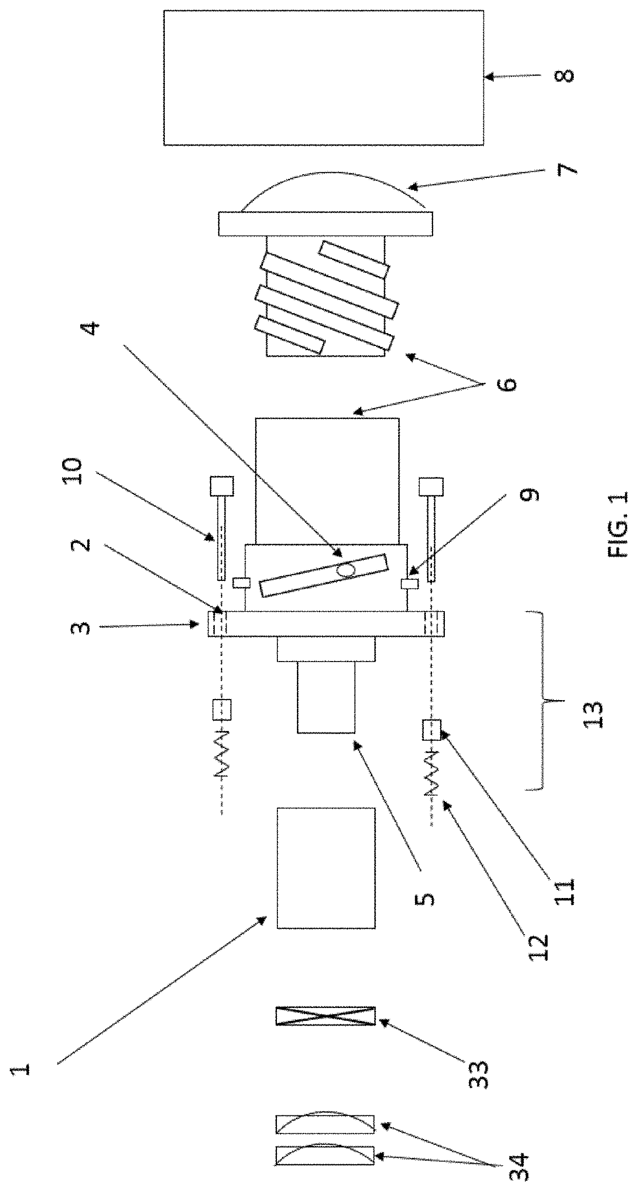
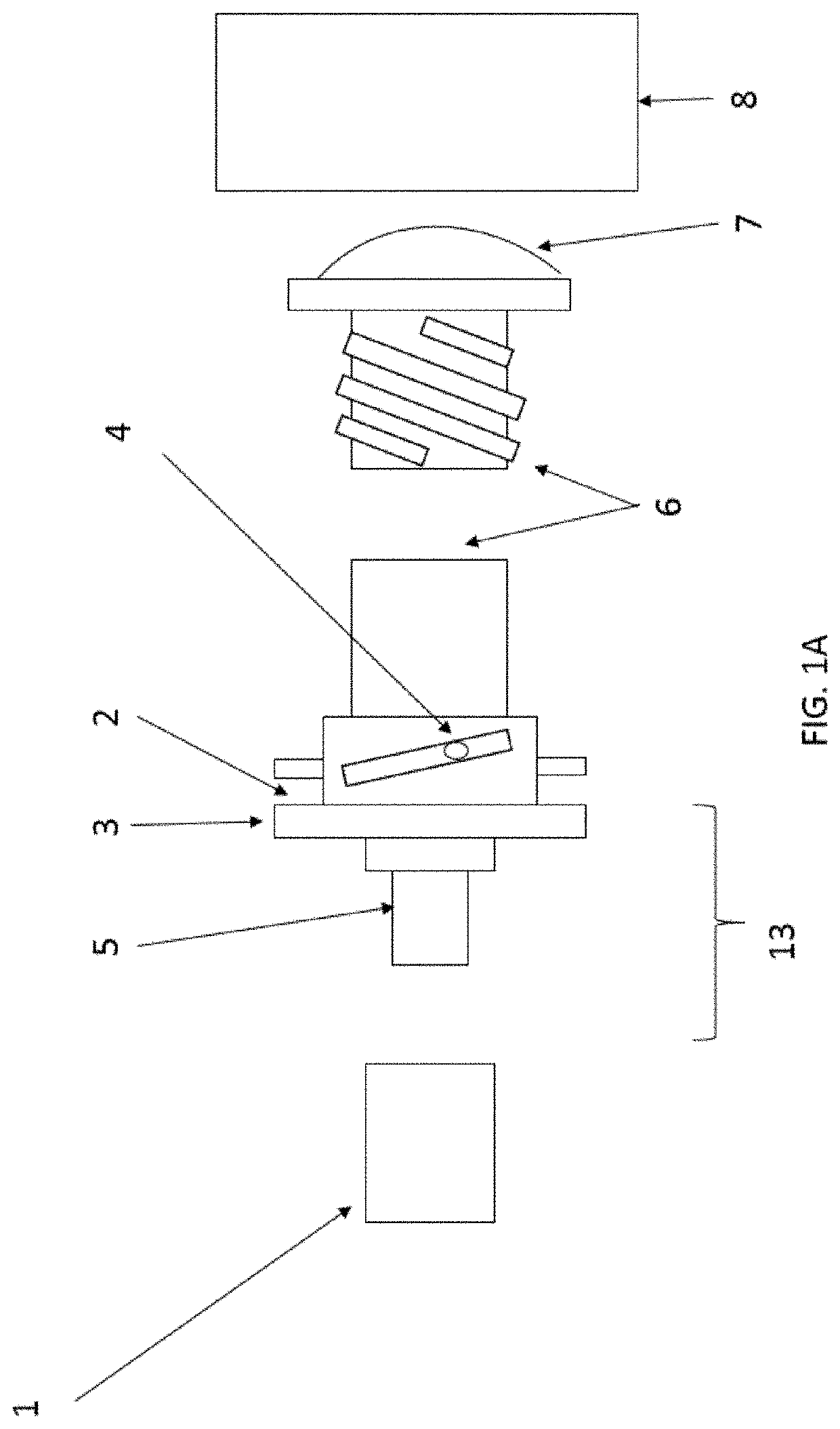
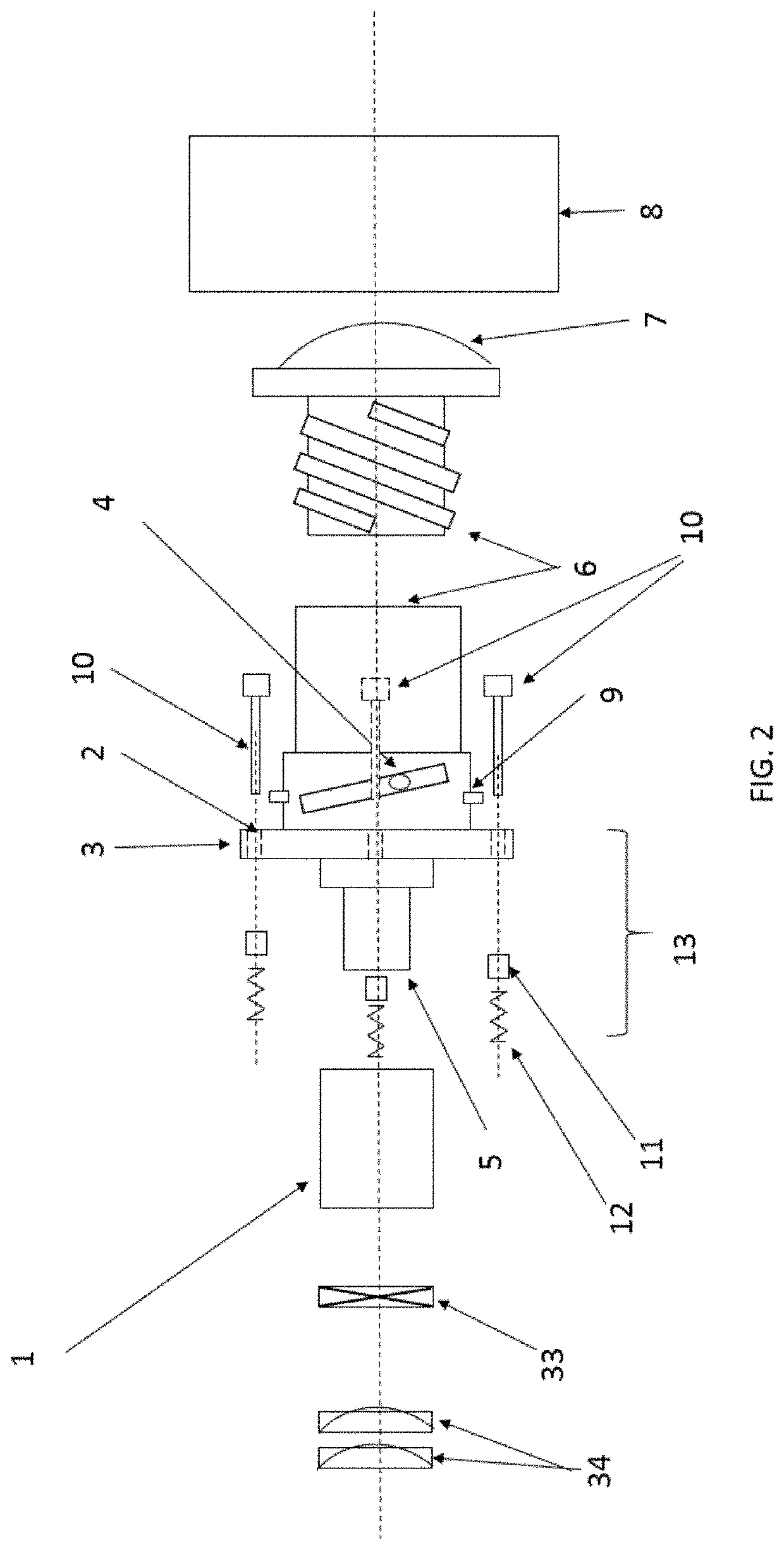
Suspension system for adjusting projected light images
a suspension system and projection light technology, applied in the direction of spring/damper functional characteristics, instruments, manufacturing tools, etc., can solve problems such as unoptimized, and achieve the effects of eliminating off-planar skews, eliminating additional stray skewings, and eliminating barrel distortion
- Summary
- Abstract
- Description
- Claims
- Application Information
AI Technical Summary
Benefits of technology
Problems solved by technology
Method used
Image

Examples
Embodiment Construction
[0039]The present invention has been described with reference to particular embodiments having various features. It will be apparent to those skilled in the art that various modifications and variations can be made in the practice of the present invention without departing from the scope or spirit of the invention. One skilled in the art will recognize that these features may be used singularly or in any combination based on the requirements and specifications of a given application or design. Embodiments comprising various features may also consist of or consist essentially of those various features. Other embodiments of the invention will be apparent to those skilled in the art from consideration of the specification and practice of the invention. The description of the invention provided is merely exemplary in nature and, thus, variations that do not depart from the essence of the invention are intended to be within the scope of the invention. All references cited in this specifi...
PUM
| Property | Measurement | Unit |
|---|---|---|
| size | aaaaa | aaaaa |
| distance | aaaaa | aaaaa |
| size | aaaaa | aaaaa |
Abstract
Description
Claims
Application Information