Eureka AIR delivers breakthrough ideas for toughest innovation challenges, trusted by R&D personnel around the world.

Phase and amplitude light pulse shaping using a one-dimensional phase mask

a phase mask and light pulse technology, applied in optics, laser details, instruments, etc., can solve the problems of increasing bulk, limiting the throughput of acousto-optic devices, and limiting the repetition rate of shaped pulses. , to achieve the effect of reducing the driving requirements of pixel pixels and small pixel pitch

Inactive Publication Date: 2009-08-18
COLORADO STATE UNIVERSITY
View PDF1 Cites 28 Cited by
  • Summary
  • Abstract
  • Description
  • Claims
  • Application Information

AI Technical Summary

Benefits of technology

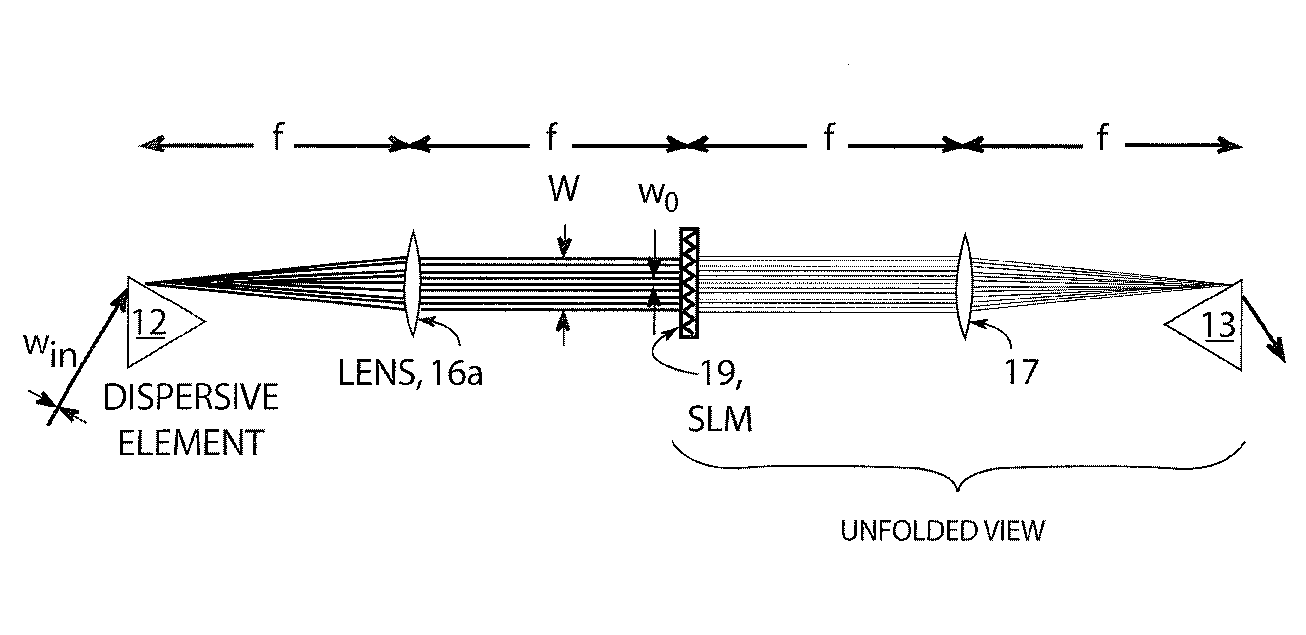
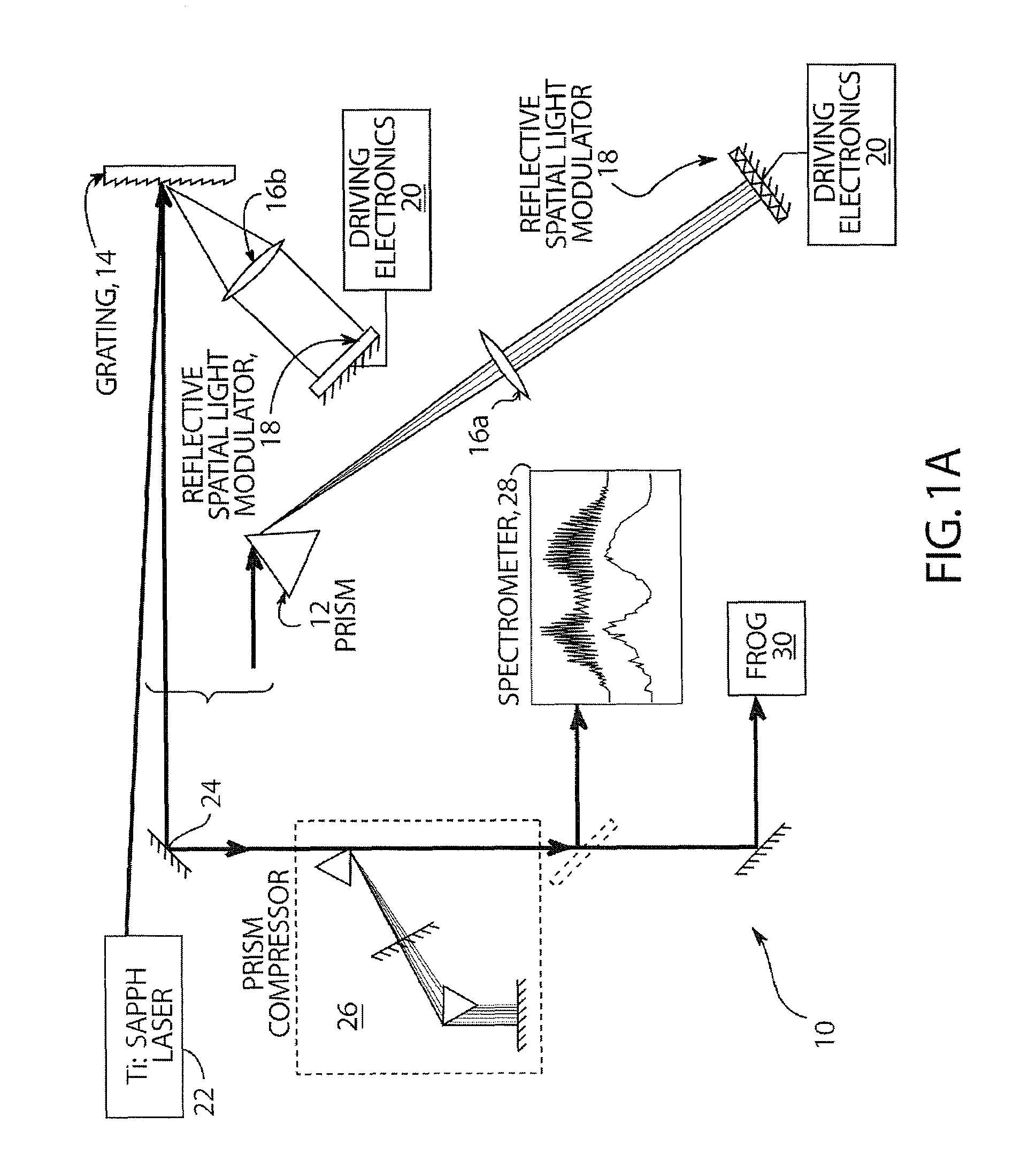
The present invention provides an apparatus and method for shaping light pulses using a single, one-dimensional phase mask. This apparatus includes a pulsed light source, a focusing element, a dispersive element, and means for generating a high spatial-frequency periodic phase grating. The method involves generating a pulsed light, dispersing it into wavelengths, and focusing it onto a chosen point. The apparatus and method can be used in various applications such as optical communication systems and optical sensors.

Problems solved by technology

Thus, the acousto-optic device throughput is fundamentally limited by the first-order diffraction efficiency, reported to be ˜50% at 620 nm in an experimental device.
AOMs can be rapidly reconfigured between pulses, but finite acoustic wave velocity places an upper limit on the repetition rate of shaped pulses.
However, two modulators are required which doubles the circuitry, increases the bulk and requires accurate alignment of the two modulators.
Additionally, the requirement for two polarizers increases losses and dispersion.

Method used


Image

  • Phase and amplitude light pulse shaping using a one-dimensional phase mask
  • Phase and amplitude light pulse shaping using a one-dimensional phase mask
  • Phase and amplitude light pulse shaping using a one-dimensional phase mask

Examples


example

[0046]As with any pulse shaping device, an accurate calibration was obtained in order to generate predictable pulse shapes. In order to characterize the phase response of the LC-SLM a functional mapping from wavelength to pixel, and drive voltage to phase was obtained. The phase grating was then analyzed for amplitude shaping to establish an effective grating spatial frequency fg and calibrating the relationship between depth of modulation Δ and transmission T.

(a) Phase Calibration:

[0047]To calibrate the device the relationship between pixel and optical frequency was determined by sweeping π-phase step across the SLM and observing the dip in the transmitted spectrum due to the phase discontinuity. A quadratic curve was fit to these data, and from the first-order coefficient of this fit, α≈28 mm rad−1 fs was estimated for the prism shaper, and α≈44 mm rad−1 fs for the grating shaper; both agree well with the theoretical values of α≈26 mm rad−1 fs and α≈44 mm rad−1 fs, respectively, c...


PUM

PropertyMeasurementUnit
optical reflectivityaaaaaaaaaa
diameteraaaaaaaaaa
focal lengthaaaaaaaaaa

Abstract

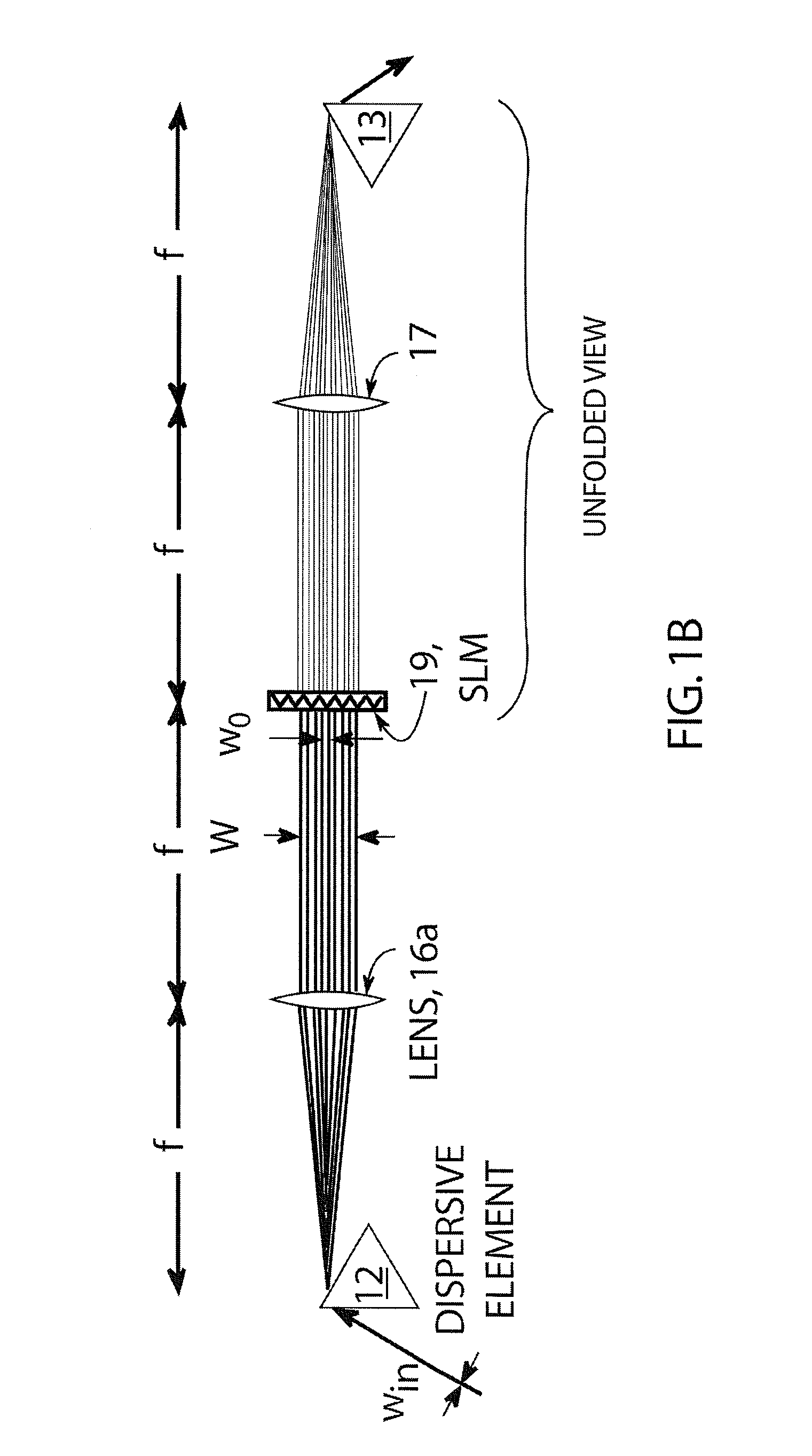
Simultaneous amplitude and phase control of ultrafast laser pulses using a single, linear (one-dimensional) liquid crystal spatial light modulator is described. Amplitude shaping is accomplished by writing a high-frequency phase grating having a spatial period much smaller than the spectral focus (over-sampling), onto the modulator, and diffracting away selected frequencies in a controllable manner, while spectral phase control is imparted by adding an appropriate slow phase bias to the modulator. The close pixel spacing, large number of pixels, and small footprint of the reflective spatial light modulator employed with an angular wavelength dispersive element in a folded Martinez stretcher, enables a simple and compact apparatus to be achieved. The high reflectivity of the spatial light modulator results in a highly efficient pulse shaper when either a prism or diffractive grating is used for the angular dispersive element. The use of a transmissive spatial light modulator in an unfolded Martinez stretcher configuration is also described.

Description

STATEMENT REGARDING FEDERAL RIGHTS[0001]This invention was made with government support under Contract Number ECS-0348068 awarded by the U.S. National Science Foundation to Colorado State University. The government has certain rights in the invention.FIELD OF THE INVENTION[0002]The present invention relates generally to light pulse shaping and, more particularly, to independent phase and amplitude shaping of ultrafast light pulses using a single, one-dimensional, high resolution liquid crystal phase mask.BACKGROUND OF THE INVENTION[0003]Programmable ultrafast optical pulse shapers are ubiquitous, with applications ranging from simple dispersion control to carefully shaped laser pulses used for coherent control of quantum dynamics, femtosecond microscopy and spectroscopy, nonlinear fiber optics, high harmonic generation, etc. While many applications utilize spectral phase-only shaping for simplicity, one also needs control over amplitude to access a complete range of temporal shapes,...

Claims


Application Information

Patent Timeline
Patent Type & Authority Patents(United States)
IPC IPC(8): G02F1/29
CPCH01S3/0057G02F1/133553G02F2203/12G02F2201/305
Inventor BARTELS, RANDY A.WILSON, JESSE W.SCHLUP, PHILIP
Owner COLORADO STATE UNIVERSITY
Why Eureka
Eureka Blog
Learn More