Photographic wide-angle lens system with internal focusing

a wide-angle lens and lens system technology, applied in the field of wide-angle lenses with internal focusing, can solve the problems of frequent limitation of optical capacity, achieve the effect of reducing the focal length of the lens system, improving optical capacity, and facilitating the installation of a motorized driv

Inactive Publication Date: 2014-11-27
JOS SCHNEIDER OPTISCHE WERKE AKTIENGESELLSCHAFT
View PDF3 Cites 14 Cited by
  • Summary
  • Abstract
  • Description
  • Claims
  • Application Information

AI Technical Summary

Benefits of technology

[0010]As a result of the aspheric configuration of the focusing array and in view of the mass of the array or the structural complexity of the array to be moved, it is possible to dispense with disadvantageous measures, such as the use of a cemented component. Instead, as provided in a preferred embodiment, it is possible to utilize a single lens, particularly a biconvex single lens, as focusing array. By the aspherization of at least one of the surfaces of the focusing array, it is possible to counteract the aberrations created in particular because of the principle of internal focusing. This will however require a compensating, likewise aspheric configuration of an element in the rear area of the lens system. For this purpose, the inventors selected the end lens of the rear array, i.e. the end element of the total lens system. A positive aspheric meniscus lens is provided specifically as end lens. This particular position is especially suitable for aspheric compensation. On the one hand, the distance between this correction lens and the detector plane of a connected camera, i.e. the rear vertex focal distance, is constant due to internal focusing, On the other, all of the aberrations introduced by the elements on the object side have totaled up to the axial position of the end lens and can be directly corrected prior to imaging in the image plane without further taking subsequent optical elements into consideration. As demonstrated further below by means of special embodiments of the invention, in this manner it is possible to achieve significantly improved optical capacity in terms of light intensity and error correction with significantly reduced focal length of the lens system. The particular advantage of the principle of internal focusing is preserved, however. In particular, the focusing array is located in the proximity of the aperture diaphragm, i.e. to the one axial position of the lens system where the beam of light has the smallest diameter. Consequently, the focusing array can also be configured with a corresponding small diameter. On the one hand, this has advantages in view of the mass to be moved during focusing; on the other, it facilitates the installation of a motorized drive, because of the smaller diameter of the focusing array, there is still sufficient installation space for a corresponding electric motor radially outside of the focusing array and still within the lens system housing, which is normally cylindrical.
[0011]In a preferred embodiment, it is provided that the front array comprises three immediately adjacent negative meniscus lenses with convex surfaces aligned on the object side. As a result of this, a high-quality retrofocus array can be realized which, as provided in a preferred embodiment, moreover has the structural advantage that all three meniscus lenses can be produced from the same type of glass.
[0012]The focusing array is arranged advantageously directly adjacent to the aperture diaphragm. As already previously mentioned, the advantage of this measure is that the focusing array is in the immediate proximity to the area of the smallest light beam diameter in the lens system. Accordingly, this will result in a very small minimum diameter of the focusing array, the consequence of which is a particularly large radial installation space for a motorized drive of the focusing array.
[0013]Alternatively to this, however, it can also be provided in another embodiment of the invention that a further lens element is arranged between the focusing array and the aperture diaphragm. Preferably, this is designed as a lens of negative refractive power, in particular a biconcave lens. This configuration will only slightly reduce the previously mentioned advantage with respect to the radial installation space, while permitting the creation of a somewhat enlarged axial installation space for the drive of the focusing array and / or for the diaphragm mechanism of the aperture diaphragm.

Problems solved by technology

A problem with such internal focusing systems however is the correction of aberrations, since during focusing, the relative distances of the central lens range to the front array and the rear array, which are essential for correction, both change.
For this reason, the resulting optical capacities are frequently limited.

Method used


Image

  • Photographic wide-angle lens system with internal focusing
  • Photographic wide-angle lens system with internal focusing
  • Photographic wide-angle lens system with internal focusing

Examples


first embodiment

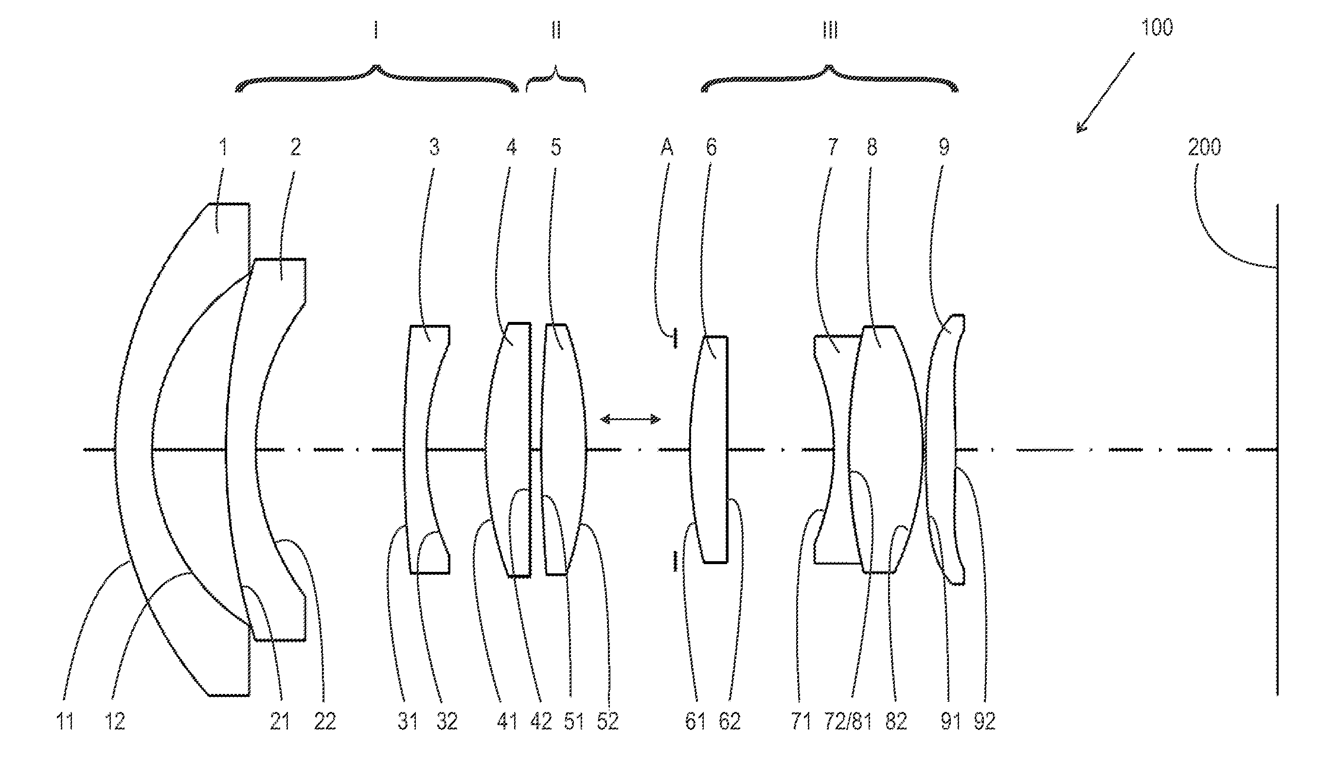
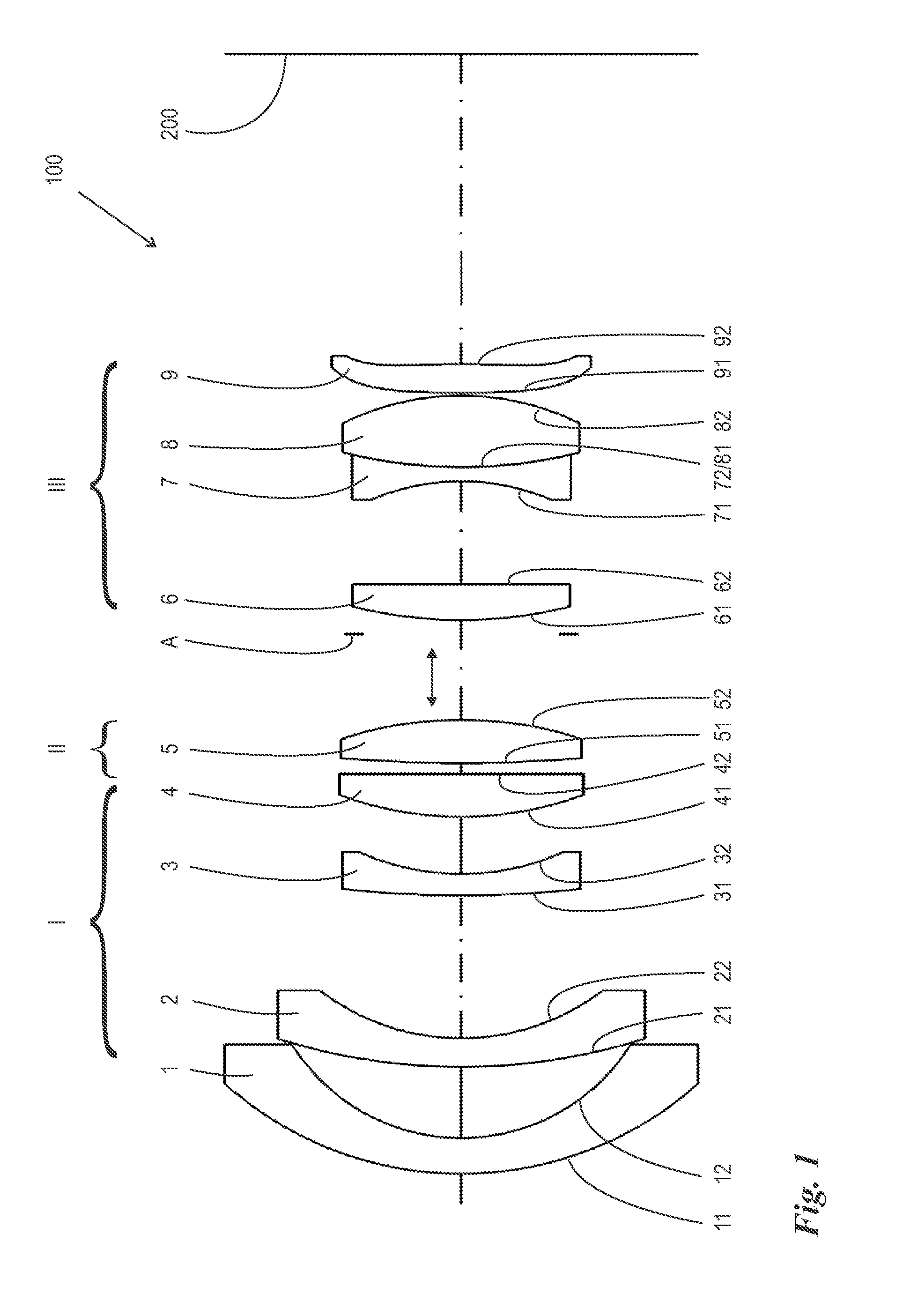
[0027]FIG. 1 illustrates a wide-angle lens system 100 according to the invention. The lens system 100 serves for imaging an object (not shown) onto an image plane 200. The lens system 100 comprises a front array I arranged on the object side, a rear array III arranged on the image side, an aperture diaphragm A arranged on the object side of the rear array III and the focusing array II arranged between the front array I and the aperture diaphragm A. The front array I comprises a first lens 1 with an object-side surface 11 and an image-side surface 12, a second lens 2 with an object-side surface 21 and an image-side surface 22, a third lens 3 with an object-side surface 31 and an image-side surface 32, as well as a fourth lens 4, with an object-side surface 41 and an image-side surface 42. The lenses 1, 2, 3, 4 of the front array I are arranged in a reciprocally rigid manner. The first lens 1 is designed as a negative meniscus lens, its object-side surface 11 comprising a larger radiu...

second embodiment

[0036]FIG. 4 illustrates a wide-angle lens system 100′. The fundamental configuration is the same as in the embodiment of FIG. 1; for that reason, when describing FIG. 4, merely the significant differences to FIG. 1 will be detailed. For the rest, reference is made to what was stated above. This specifically also applies to the reference signs introduced and used in conjunction with FIG. 1 and also with FIG. 4.

[0037]The basic configuration of the embodiment of FIG. 4 compared to the basic configuration of the embodiment of FIG. 1 is characterized above all in that the front array I consists merely of three negative meniscus lenses 1, 2, 3. A fourth lens of the front array I is not provided in the embodiment of FIG. 4. The fact that the fourth lens is absent is compensated by the introduction of a further aspheric surface, namely the object-side surface 61 of the sixth lens 6, as shown in the following Table 2. The absence of the fourth lens cannot be compensated completely, however,...

third embodiment

[0043]FIG. 7 shows a lens system 100″ according to the invention which likewise essentially has the same basic configuration as the embodiment of FIG. 1, which is why here as well only the differences from the embodiment of FIG. 1 will be dealt with. For the rest, reference can be made to what has been stated above. In particular, the same reference signs will be used that were already introduced in conjunction with FIG. 1.

[0044]The basic configuration of the lens system 100″ according to FIG. 7 differs from the one of the lens system 100 of FIG. 1 primarily because of an additional tenth lens 10, which, as a negative lens, particularly as a biconcave lens, in particular as a biconcave lens the object-side surface 101 of which has a larger radius of curvature than its image-side surface 102. This additional tenth lens 10 permits a reduction in the number of aspheric surfaces by one. Preferably, the image-side surface 52 of the focusing lens, i.e. the fifth lens 5, is designed spheri...


PUM


Abstract

A photographic wide-angle lens system with internal focusing has a front array (II) of negative refractive power that is rigid within itself and fixed on the object-side, a rear array (III) of positive refractive power that is rigid within itself and fixed on the image side of an aperture diaphragm (A), and a focusing array (II) of positive refractive power having an optical single element (5) that is arranged between the front array (I) and the aperture diaphragm A and is axially movable from a maximum axial position on the object side to a maximum axial position on the image side to vary the focus distance from its maximum to its minimum value. The optical single element of the focusing array (II) has at least one aspheric surface (51, 52) and the image-side end lens (9) of the rear array (III) is configured as a positive, aspheric meniscus lens.

Description

BACKGROUND[0001]1. Field of the Invention[0002]The invention relates to a photographic wide-angle lens with internal focusing, comprising three lens arrays, namely a front array of negative refractive power that is rigid within itself and is fixed on the object-side, a rear array of positive refractive power that is rigid within itself and is fixed on the image side of an aperture diaphragm, and a focusing array of positive refractive power consisting of an optical single element that is arranged between the front array and the aperture diaphragm and is axially movable, the linear displacement of which from a maximum axial position on the object side to a maximum axial position on the image side allows to vary the focal distance from its maximum to its minimum value.[0003]2. Description of the Related Art[0004]Wide-angle lens systems of this type are known from U.S. Pat. No. 6,545,824 B2.[0005]The known lens system comprises a front array that is configured in the traditional manner...

Claims


Application Information

Patent Timeline
Patent Type & Authority Applications(United States)
IPC IPC(8): G02B13/04
CPCG02B13/04G02B7/04G02B9/64G02B13/18
Inventor WANG, LINGLISHYSHKIN, IHAR
Owner JOS SCHNEIDER OPTISCHE WERKE AKTIENGESELLSCHAFT
Why Eureka
Try Eureka