Large aperture imaging optical system

a technology of optical systems and large apertures, applied in optics, telescopes, instruments, etc., can solve the problems of difficult or impossible correction of secondary spectrum, severely limit off-axis performance at wide apertures, and general mediocrity of high-speed wide-angle examples, etc., to achieve the effect of improving performan

Inactive Publication Date: 2009-02-26
CALDWELL PHOTOGRAPHIC
View PDF23 Cites 16 Cited by
  • Summary
  • Abstract
  • Description
  • Claims
  • Application Information

AI Technical Summary

Benefits of technology

[0021]A lens designed according to the present invention for cinematographic or general photographic applications may be applied to applications requiring only a narrow range of magnifications simply because the broad magnification range of the design encompasses the magnification range required for the application at hand. However, it is generally be better to optimize an optical system to work best under the actual conditions in which it is used. So, for example, an aerial reconnaissance lens should be optimized to perform best at infinite or nearly infinite conjugates, and this performance need not be compromised to improve performance for closer object distances.
[0022]Surveillance and reconnaissance lenses are also often required to work well over an extended waveband that includes the near-infrared portion of the spectrum. This allows for improved imagery through haze and atmospheric scattering, and it also permits the use of specialized sensors for low-light applications.

Problems solved by technology

However, double-Gauss designs rely on the use of positive elements made of high index crown glass in order to flatten the field, and as a result it is difficult or impossible to correct the secondary spectrum.
Double-Gauss designs also have a strong tendency to suffer from oblique spherical aberration that severely limits off-axis performance at wide apertures.
However, the image quality for high-speed wide-angle examples is generally mediocre, and these lenses need to be stopped down substantially to achieve good results.
Despite the above efforts, virtually all high-speed photographic lenses designed to date are compromised by the need to balance large aberrations against each other.

Method used


Image

  • Large aperture imaging optical system
  • Large aperture imaging optical system
  • Large aperture imaging optical system

Examples


example 1

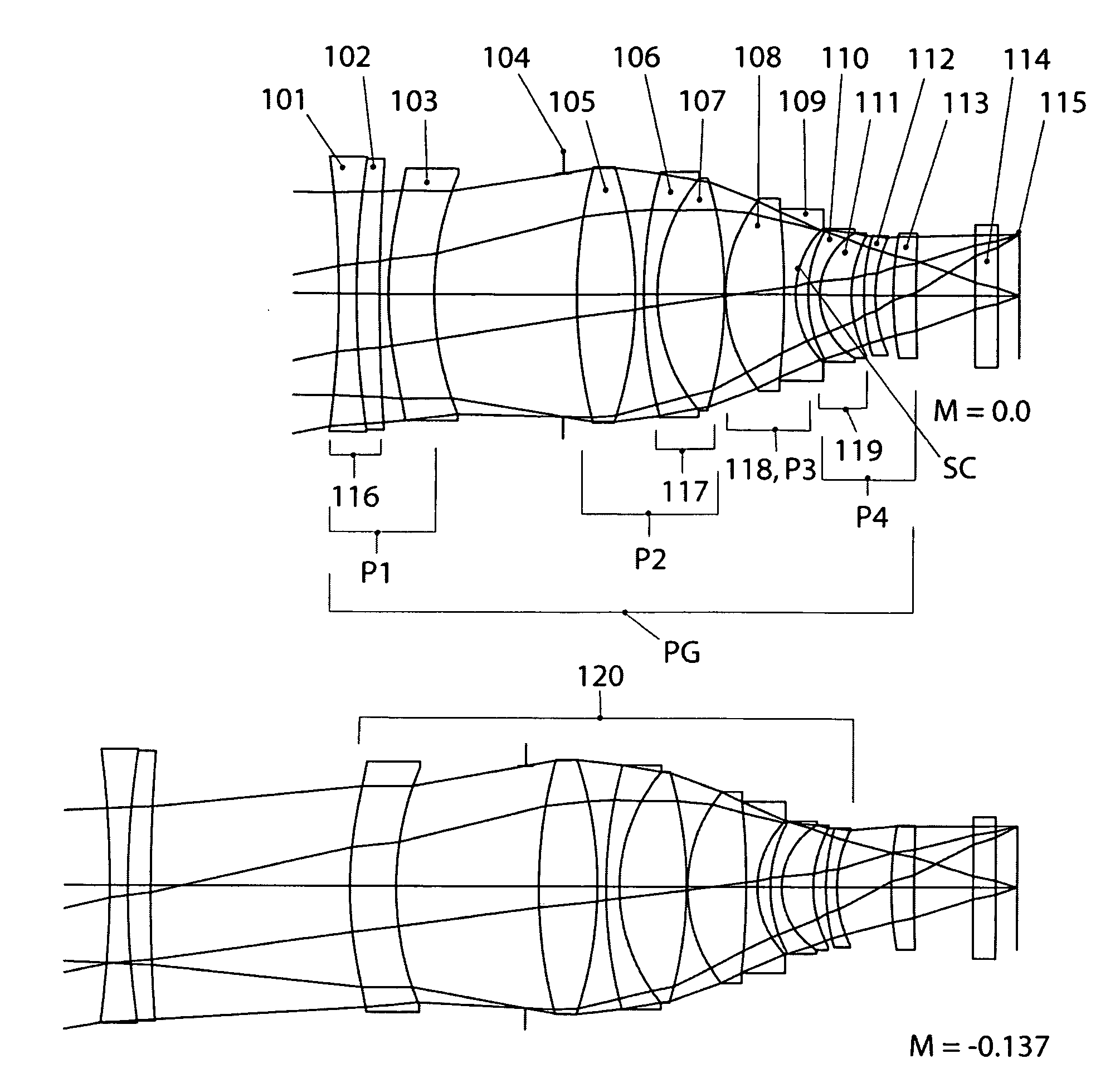
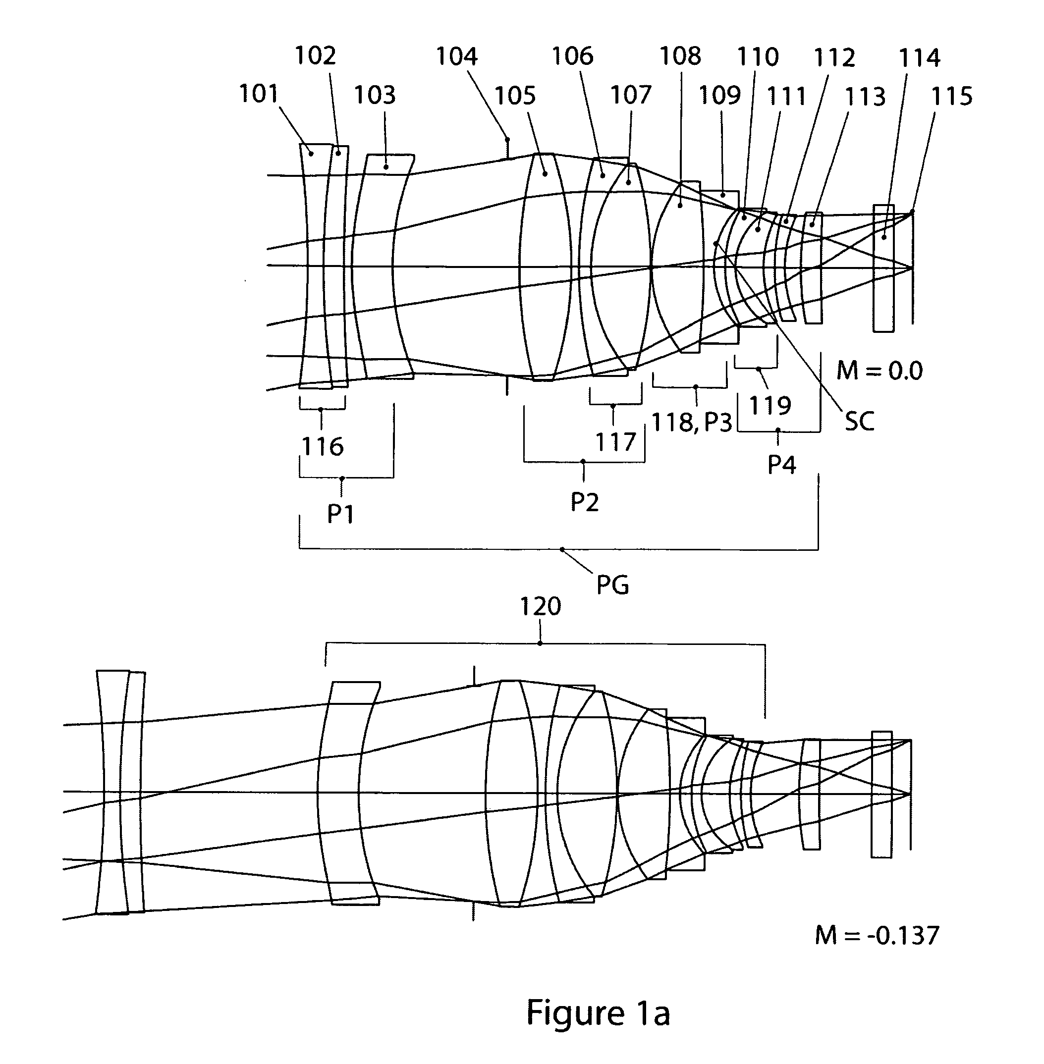
[0079]Example 1, which is a 65 mm focal length objective for 35 mm format cinematography, is illustrated in FIG. 1a, which shows cross-sectional layouts at magnifications of 0 and −0.137×. All of the element and group designations mentioned below are shown in FIG. 1a. The relative aperture is f / 1.33, the image diagonal is 28 mm, and the diagonal field of view (FOV) is 24.3 degrees.

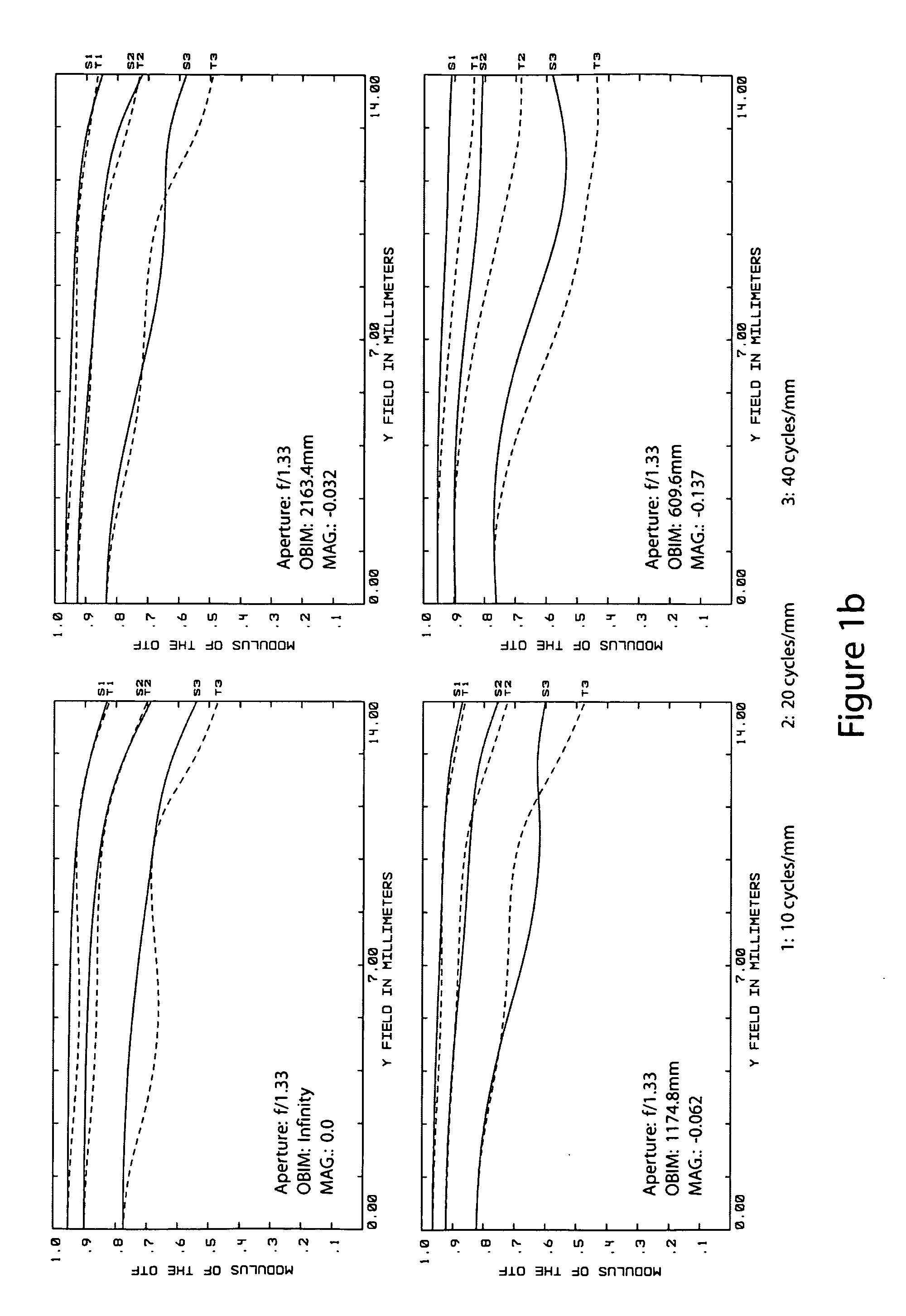
[0080]MTF vs. Image Height at 10, 20 and 40 cycles / mm for four different object distances is illustrated in FIG. 1b. These curves indicate that Example 1 is extremely well corrected at f / 1.33, with MTF values at 40 cycles / mm greater than 80% near the optical axis in the middle part of the focusing range and very near 80% at the extreme ends of the focusing range. This extraordinary performance falls off very gradually to the corner of the field, and the S and T curves stay close together. FIG. 1c shows distortion and astigmatism (Coddington curves) for the same four object distances used in FIG. 1b. Distor...

example 2

[0092]Example 2, which is a 65 mm focal length objective for 35 mm format cinematography, is illustrated in FIG. 2a, which shows cross-sectional layouts at magnifications of 0 and −0.124×. All of the element and group designations mentioned below are shown in FIG. 1a. The relative aperture is f / 1.4, the image diagonal is 28 mm, and the diagonal field of view (FOV) is 24.3 degrees.

[0093]MTF vs. Image Height at 10, 20 and 40 cycles / mm for four different object distances is illustrated in FIG. 2b. These curves indicate that Example 2 is extremely well corrected at f / 1.4, with MTF values at 40 cycles / mm greater than 80% near the optical axis in the middle part of the focusing range and very near 80% at closest focus. This extraordinary performance falls off very gradually to the corner of the field, and the S and T curves stay close together. FIG. 2c shows distortion and astigmatism (Coddington curves) for the same four object distances used in FIG. 2b. Distortion is less than 1% at all...

example 3

[0101]Example 3, which is a 65 mm focal length objective for 35 mm format cinematography, is illustrated in FIG. 3a, which shows cross-sectional layout. All of the element and group designations mentioned below are shown in FIG. 3a. The relative aperture is f / 1.4, the image diagonal is 28 mm, and the diagonal field of view (FOV) is 24.3 degrees.

[0102]MTF vs. Image Height at 10, 20 and 40 cycles / mm is illustrated in FIG. 3b. These curves indicate that Example 3 is extremely well corrected at f / 1.4, with MTF values at 40 cycles / mm well above 80% over the majority of the image circle. This extraordinary performance falls off very gradually to the corner of the field, and the S and T curves stay extremely close together. FIG. 3c shows distortion and astigmatism (Coddington curves). Both Distortion and astigmatism are virtually zero, and there is just a trace of field curvature. FIG. 3d is a plot of relative illumination vs. image height at f / 1.4 and f / 2.8, and it indicates that the Exam...


PUM


Abstract

Large aperture optical systems that are extremely well corrected over a large flat field and over a large spectral range are disclosed. Breathing and aberration variation during focusing are optionally controlled by moving at least two groups of lens elements independently. Aberration correction in general is aided by allowing the working distance to become short relative to the format diagonal. Field curvature is largely corrected by a steeply curved concave surface relatively close to the image plane. This allows the main collective elements to be made of low-index anomalous dispersion materials in order to correct secondary spectrum. In wide-angle example embodiments, distortion may be controlled with an aspheric surface near the front of the lens.

Description

CLAIM OF PRIORITY[0001]This application claims the benefit of priority under 35 U.S.C. §119(e) of U.S. Provisional Application Ser. No. 60 / 966036 filed on Aug. 24, 2007.FIELD OF THE INVENTION[0002]The present invention relates to the field of large aperture imaging optics, and more specifically relates to photographic, cinematographic and reconnaissance optical systems that are extremely well corrected at a relative aperture of about f / 1.5 or faster over a full field of view of approximately 5 degrees or more throughout a large spectral range. The present invention also relates to the field of cinematographic optical systems that are well corrected for breathing over a wide magnification range.BACKGROUND ART[0003]A long sought-after goal of photographic optical design is to provide a large aperture objective having an f / number of about f / 1.5 or smaller that is well corrected for all aberrations over a large flat field and over a large spectral range. In addition, a goal for objectiv...

Claims


Application Information

Patent Timeline
Patent Type & Authority Applications(United States)
IPC IPC(8): G02B9/12G02B9/60
CPCG02B13/20G02B13/18
Inventor CALDWELL, J. BRIAN
Owner CALDWELL PHOTOGRAPHIC
Why Eureka
Try Eureka