Three dimensional, low friction vasoocclusive coil, and method of manufacture

a vasoocclusive coil and low-friction technology, applied in the field of vasoocclusive devices, can solve the problems of inherently more difficult, misalignment of the coil within the catheter, etc., and achieve the effect of reducing coil friction and preventing coil realignment or misalignmen

Inactive Publication Date: 2014-07-29
DEPUY SYNTHES PROD INC
View PDF155 Cites 7 Cited by
  • Summary
  • Abstract
  • Description
  • Claims
  • Application Information

AI Technical Summary

Problems solved by technology

However, due to the tendency of such three dimensional shaped coils to transform into their expanded, final forms when introduced into a catheter in the body, they are inherently more difficult than a helical coil or a straight wire or micro-cable to push through such a catheter for delivery to a site in the vasculature to be treated, due to friction between the coil and the catheter through which it is delivered to the site to be treated, which can even result in misalignment of the coil within the catheter during delivery.

Method used


Image

  • Three dimensional, low friction vasoocclusive coil, and method of manufacture
  • Three dimensional, low friction vasoocclusive coil, and method of manufacture
  • Three dimensional, low friction vasoocclusive coil, and method of manufacture

Examples


Embodiment Construction

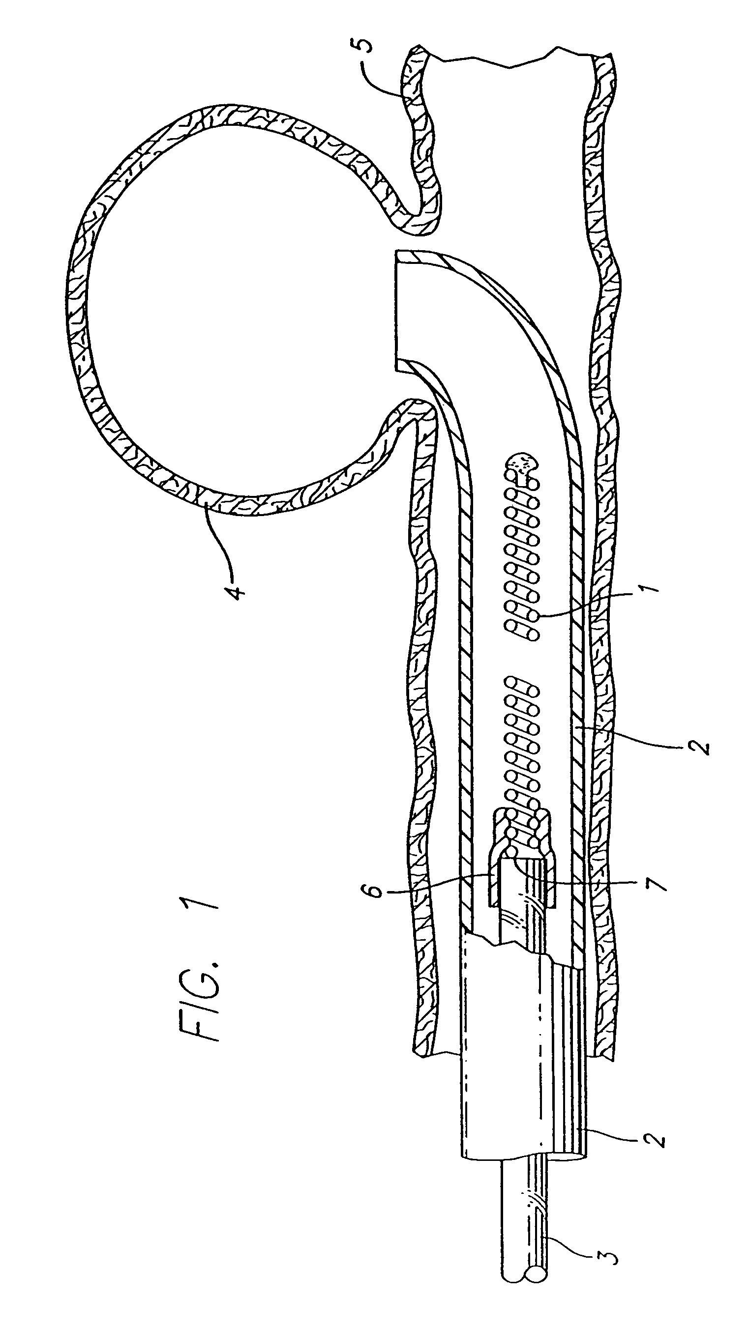
[0035]While conventional three dimensional and spherical vasoocclusive coils have been developed, such three dimensional shaped coils tend to transform into their expanded, final forms when introduced into a catheter in the body, making them inherently more difficult than a simple helical coil or straight wire to push through a catheter or cannula for delivery to a site in the vasculature to be treated, due to friction between the coil and the catheter through which it is delivered to the site to be treated, and that can even result in misalignment of the coil within the catheter during delivery.

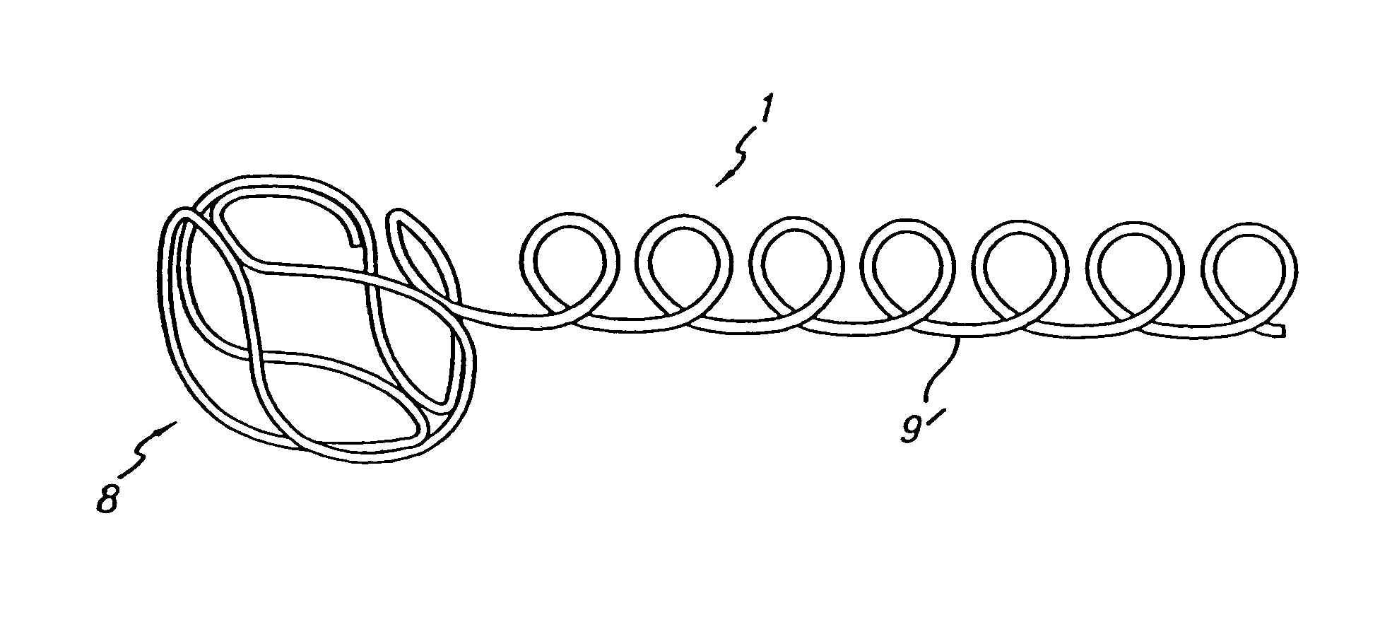
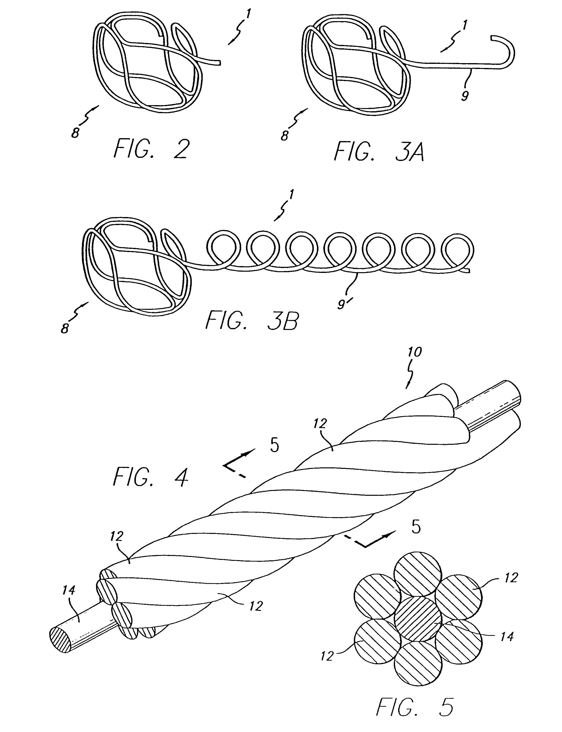
[0036]As is illustrated in the drawings, the invention is accordingly embodied in a vasoocclusive device that is adapted to be inserted into a portion of a vasculature for occluding the portion of the vasculature for use in interventional therapy and vascular surgery. The vasoocclusive coil 1 is formed from at least one strand of a flexible material formed to have a first inoperable, substan...


PUM


Abstract

The three dimensional, low friction vasoocclusive coil has a portion that is three dimensionally box or cubed shaped. The three dimensional box or cubed shaped portion will form a basket for filling the anatomical cavity at the site in the vasculature to be treated. The vasoocclusive device is formed from at least one strand of a flexible material formed to have a first inoperable, substantially linear configuration for insertion into and through a catheter or cannula to a desired portion of the vasculature to be treated, and a second operable, three dimensional configuration for occluding the desired portion of the vasculature to be treated. The vasoocclusive coil may optionally include a portion that is substantially J-shaped or helically shaped, for filling and reinforcing the three dimensional portion.

Description

RELATED APPLICATIONS[0001]This is a continuation of application Ser. No. 10 / 664,001, filed 16 Sep. 2003, now U.S. Pat. No. 7,316,701, which is a continuation of application Ser. No. 09 / 590,794, filed Jun. 8, 2000, now U.S. Pat. No. 6,638,291, which is a continuation-in-part of application Ser. No. 09 / 140,495, filed 27 Aug. 1998, now U.S. Pat. No. 6,171,326, and application Ser. No. 09 / 089,328, filed 2 Jun. 1998, now U.S. Pat. No. 6,090,125, which is a continuation of application Ser. No. 08 / 799,439, filed 13Feb. 1997, now U.S. Pat. No. 5,766,219, which is a continuation of application Ser. No. 08 / 425,106, filed 20 Apr. 1995, now U.S. Pat. No. 5,645,558.BACKGROUND OF THE INVENTION[0002]1. Field of the Invention[0003]This invention relates generally to vasoocclusive devices, and more particularly concerns a vasoocclusive device that has a first elongated, reduced friction configuration in which the vasoocclusive device may be deployed through a catheter or cannula to an anatomical cav...

Claims


Application Information

Patent Timeline
Patent Type & Authority Patents(United States)
IPC IPC(8): A61M29/00
CPCA61B17/12022A61B17/12113A61B17/12145A61B2017/1205A61B2017/12072A61B2017/12077
Inventor FERRERA, DAVID A.KURZ, DANIELWILSON, PETERSEIN-LWYN, CRYSTAL K.LEI, LOK A.HORTON, JOSEPH A.
Owner DEPUY SYNTHES PROD INC
Why Eureka
Try Eureka