Transfer medium manufacturing method, transfer method, transfer medium manufacturing apparatus, and transfer apparatus

a technology of transfer target medium and manufacturing method, which is applied in the direction of thermography, instruments, mechanical control devices, etc., can solve the problems of insufficient gloss of metallic foil formed on the transfer target medium by metallic ink, the form of complex recorded image on the base material remains almost undisturbed, and the hardening of metal ink upon the surface of intermediate transfer recording medium in a bumpy sta

Active Publication Date: 2014-08-12
SEIKO EPSON CORP
View PDF8 Cites 0 Cited by
  • Summary
  • Abstract
  • Description
  • Claims
  • Application Information

AI Technical Summary

Benefits of technology

[0007]An advantage of some aspects of the invention is to provide a transfer medium manufacturing method, a transfer method, a transfer medium manufacturing apparatus, and a transfer apparatus capable of achieving sufficient glossiness in a metallic foil transferred from a transfer medium onto a target.
[0009]According to the aforementioned configuration, the surface of the foil forming recording material, which is in a partially-melted state, is smoothed by a smoothing unit in a smooth manner. Note that the surface of the foil forming recording material that is smoothed by the smoothing unit is the surface that makes contact with the target. Accordingly, transferring the foil forming recording material onto the target as a metallic foil makes it possible to obtain a metallic foil that has sufficient glossiness when viewed over the target.
[0011]According to this configuration, the same effects as those of the aforementioned transfer medium manufacturing method can be achieved.
[0013]According to this configuration, the same effects as those of the aforementioned transfer medium manufacturing method can be achieved.
[0015]According to this configuration, in the case where, for example, the foil forming recording material forms a complex recorded image upon the base material, the biasing force applied to the pressing unit by the biasing unit is reduced. As a result, the pressing unit presses weakly upon the recorded image, and thus the form of the complex recorded image upon the base material remains almost undisturbed. On the other hand, in the case where, for example, the foil forming recording material forms a simple recorded image upon the base material, the biasing force applied to the pressing unit by the biasing unit is increased. As a result, the pressing unit presses strongly upon the recorded image, thus making it possible to smooth the surface of the foil forming recording material with more certainty.
[0019]According to this configuration, the same effects as those of the aforementioned transfer medium manufacturing apparatus can be achieved.

Problems solved by technology

However, there may be situations where, when the printing unit ejects a metallic ink onto the intermediate transfer recording medium, the metallic ink hardens upon the surface of the intermediate transfer recording medium in a bumpy state.
There has thus been the risk that if the metallic ink is transferred onto the transfer target medium in a state in which the contact surface has poor planarity relative to the transfer target medium, the metallic foil formed upon the transfer target medium by the metallic ink will have insufficient glossiness when viewed over the transfer target medium.
As a result, the pressing unit presses weakly upon the recorded image, and thus the form of the complex recorded image upon the base material remains almost undisturbed.

Method used


Image

  • Transfer medium manufacturing method, transfer method, transfer medium manufacturing apparatus, and transfer apparatus
  • Transfer medium manufacturing method, transfer method, transfer medium manufacturing apparatus, and transfer apparatus
  • Transfer medium manufacturing method, transfer method, transfer medium manufacturing apparatus, and transfer apparatus

Examples


Embodiment Construction

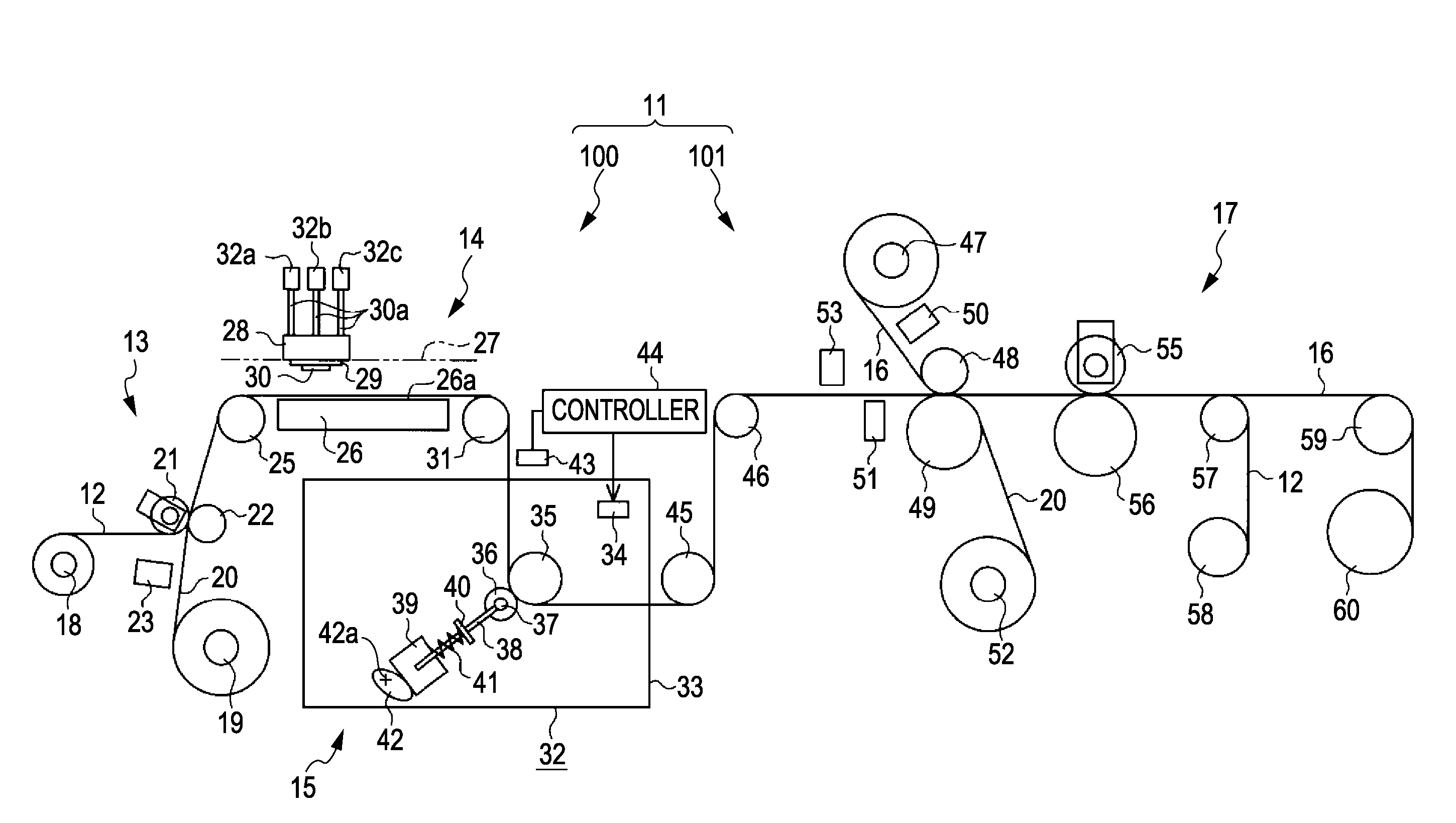
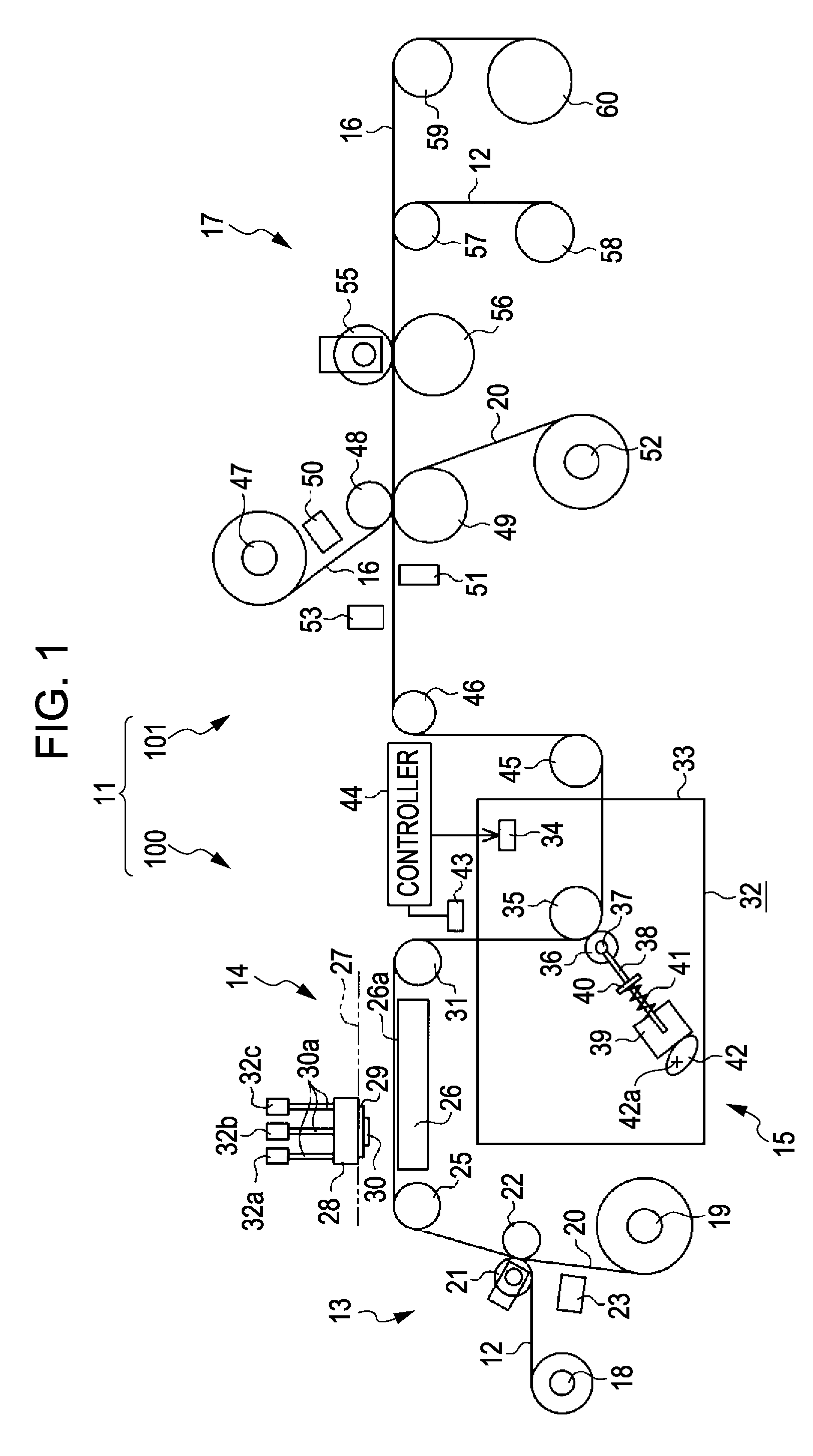
[0025]Hereinafter, a transfer apparatus serving as a specific embodiment of the invention will be described based on the drawings. Note that the terms “longitudinal direction,”“horizontal direction,” and “vertical direction” used in the following descriptions are based on the directions indicated by arrows in FIG. 1.

[0026]As shown in FIG. 1, a transfer apparatus 11 is configured of a transfer medium manufacturing apparatus 100 for manufacturing a transfer medium in which an image pattern has been formed on a base material film 12 serving as a base material, and a transfer unit 101 that transfers the image pattern from the transfer medium manufactured by the transfer medium manufacturing apparatus 100 onto a transfer target medium serving as a target. The transfer medium manufacturing apparatus 100, meanwhile, includes: an unwinding unit 13 that unwinds the base material film 12, which is in the shape of a continuous long sheet; a printing unit 14 that forms the image pattern upon th...


PUM

PropertyMeasurementUnit
pressureaaaaaaaaaa
biasing forceaaaaaaaaaa
temperatureaaaaaaaaaa

Abstract

A transfer medium manufacturing method for manufacturing a transfer medium in which a foil forming recording material containing metallic particles capable of being transferred onto a target has been applied to a base material includes: applying the foil forming recording material to the base material; and smoothing the surface of the foil forming recording material applied to the base material in the applying, the foil forming recording material being in a partially-melted state.

Description

BACKGROUND[0001]1. Technical Field[0002]The present invention relates to a transfer medium manufacturing method for manufacturing a transfer medium by applying a foil forming recording material, containing metallic particles capable of being transferred onto a target, to a base material, a transfer method that uses a transfer medium manufactured through the stated transfer medium manufacturing method, a transfer medium manufacturing apparatus, and a transfer apparatus.[0003]2. Related Art[0004]Thermal transfer apparatuses are widely known as a type of transfer apparatus that transfers a recording material from a transfer medium onto a target (for example, see JP-A-2008-188865). The thermal transfer apparatus disclosed in JP-A-2008-188865 includes a printing unit that forms an image by ejecting ink (a foil forming recording material) onto an intermediate transfer recording medium (a transfer medium) and a transfer section that heat-transfers the image formed by the printing unit from...

Claims


Application Information

Patent Timeline
Patent Type & Authority Patents(United States)
IPC IPC(8): B05C11/00B32B41/00
CPCB41M5/465Y10T156/1707B41M7/0072B41M5/385B41M5/40
Inventor MATSUHASHI, KUNIHIKO
Owner SEIKO EPSON CORP
Why Eureka
Try Eureka