Control panel for fitness equipment

a technology for controlling panels and fitness equipment, applied in the direction of gymnastic exercise, contact mechanisms, electrical devices, etc., can solve the problems of inconvenient use, and achieve the effect of convenient turning

Inactive Publication Date: 2014-09-09
PARADIGM HEALTH & WELLNESS
View PDF8 Cites 23 Cited by
  • Summary
  • Abstract
  • Description
  • Claims
  • Application Information

AI Technical Summary

Benefits of technology

[0009]A control panel for fitness equipment has a board, a screen, a rotary knob switch and a wire. The board has an inner surface and an outer surface. The screen is securely mounted on the outer surface of the board. The rotary knob switch is rotatably mounted through the board beside the screen and has a held end and a wire end opposite to the held end. The wire has an end that is securely mounted at the wire end of the rotary knob switch. Accordingly, the rotary knob switch can be directly and conveniently turned at the board.

Problems solved by technology

Because the conventional rotary knob switch is located a lower position on the fitness equipment, the user has to bend down to turn the rotary knob switch during exercise, and this is dangerous, especially for the elderly.
Otherwise, the user has to turn off the fitness equipment before turning the conventional rotary knob switch, and this is inconvenient in use.

Method used


Image

  • Control panel for fitness equipment
  • Control panel for fitness equipment
  • Control panel for fitness equipment

Examples


Embodiment Construction

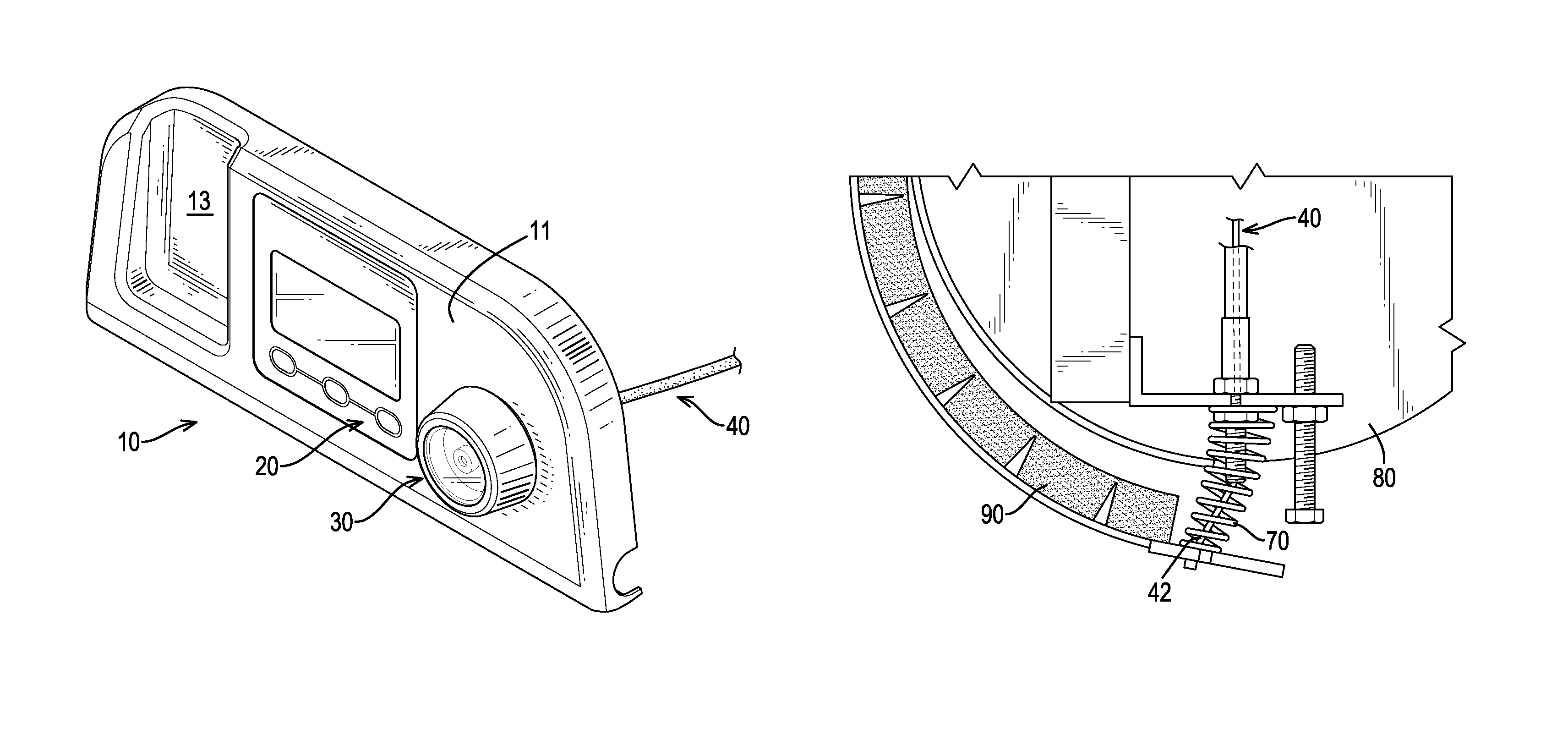
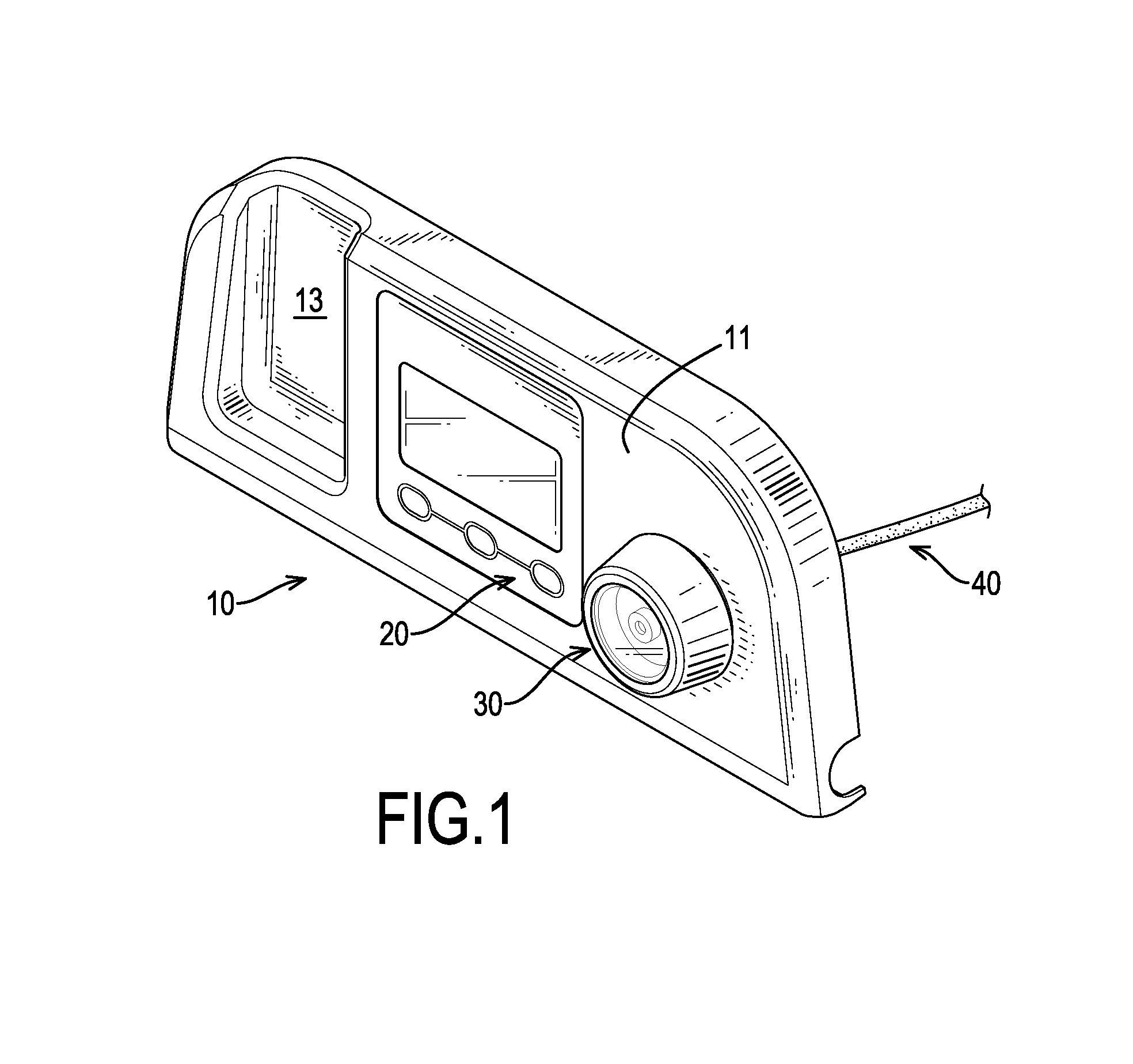
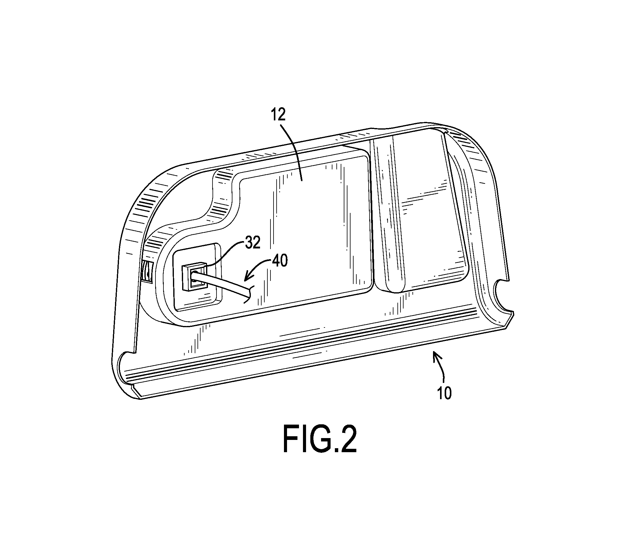
[0018]With reference to FIGS. 1 to 4, a control panel for fitness equipment in accordance with the present invention comprises a board 10, a screen 20, a rotary knob switch 30 and a wire 40. The board 10 has an outer surface 11 and an inner surface 12. The inner surface 12 is opposite to the outer surface 11 of the board 10. Preferably, the board 10 has a receiving recess 13 formed in the outer surface 11 of the board 10. The receiving recess 13 is used to receive a mobile phone or a water bottle.

[0019]The screen 20 is securely mounted on the outer surface 11 of the board 10. The rotary knob switch 30 is rotatably mounted through the board 10 beside the screen 20 and the receiving recess 13. The rotary knob switch 30 has a held end 31 and a wire end 32. The held end 31 of the rotary knob switch 30 is adjacent to the outer surface 11 of the board 10. The wire end 32 is opposite to the held end 31 and is adjacent to the inner surface 12 of the board 10. The wire 40 is securely connect...


PUM


Abstract

A control panel for fitness equipment has a board, a screen, a rotary knob switch and a wire. The board has an inner surface and an outer surface. The screen is securely mounted on the outer surface of the board. The rotary knob switch is rotatably mounted through the board beside the screen and has a held end and a wire end opposite to the held end. The wire has an end that is securely mounted at the wire end of the rotary knob switch. Accordingly, the rotary knob switch can be directly and conveniently turned at the board.

Description

BACKGROUND OF THE INVENTION[0001]1. Field of the Invention[0002]The present invention relates to a control panel for fitness equipment, and more particularly to a control panel having a rotary knob switch.[0003]2. Description of Related Art[0004]A conventional fitness equipment, such as a treadmill, a gym bike or an elliptical trainer, usually has a rotary knob switch used to adjust resistance of the fitness equipment. When the conventional rotary knob switch is turned, the rotary knob switch pulls a wire and the wire pulls a magnet device. Consequently, the magnet device is pivoted upward and approaches a wheel. With the change of magnet force between the wheel and the magnet device, the resistance of the fitness equipment can be adjusted.[0005]However, the conventional rotary knob switch is located below a user or located at a side surface of the fitness equipment. For example, the conventional rotary knob switch is mounted on a treadmill base at a position below the user, or is m...

Claims


Application Information

Patent Timeline
Patent Type & Authority Patents(United States)
IPC IPC(8): H01H3/08H01H19/00
CPCA63B21/00069A63B22/0605A63B21/0051A63B22/02H01H19/14
Inventor WEI, TSAO-KUANG
Owner PARADIGM HEALTH & WELLNESS
Why Eureka
Try Eureka