
Tube squeezing device

a tube and tube technology, applied in the field of tube squeezing devices, can solve the problems of essentially wasted product in the tube, difficult to remove liquid or paste-like contents from the tube, and material or product left in the tube, and achieve the effects of convenient product removal, convenient product removal, and effective advancement of material

Active Publication Date: 2022-10-11
BUCKLEY WAYNE
View PDF26 Cites 0 Cited by
  • Summary
  • Abstract
  • Description
  • Claims
  • Application Information

AI Technical Summary

Benefits of technology

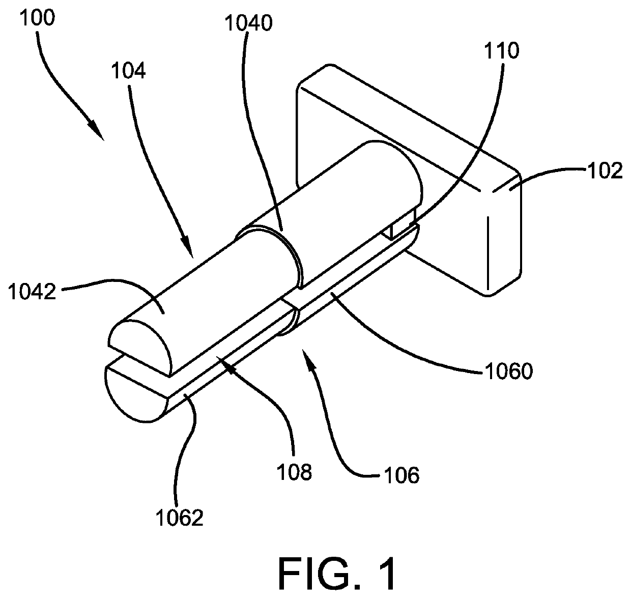
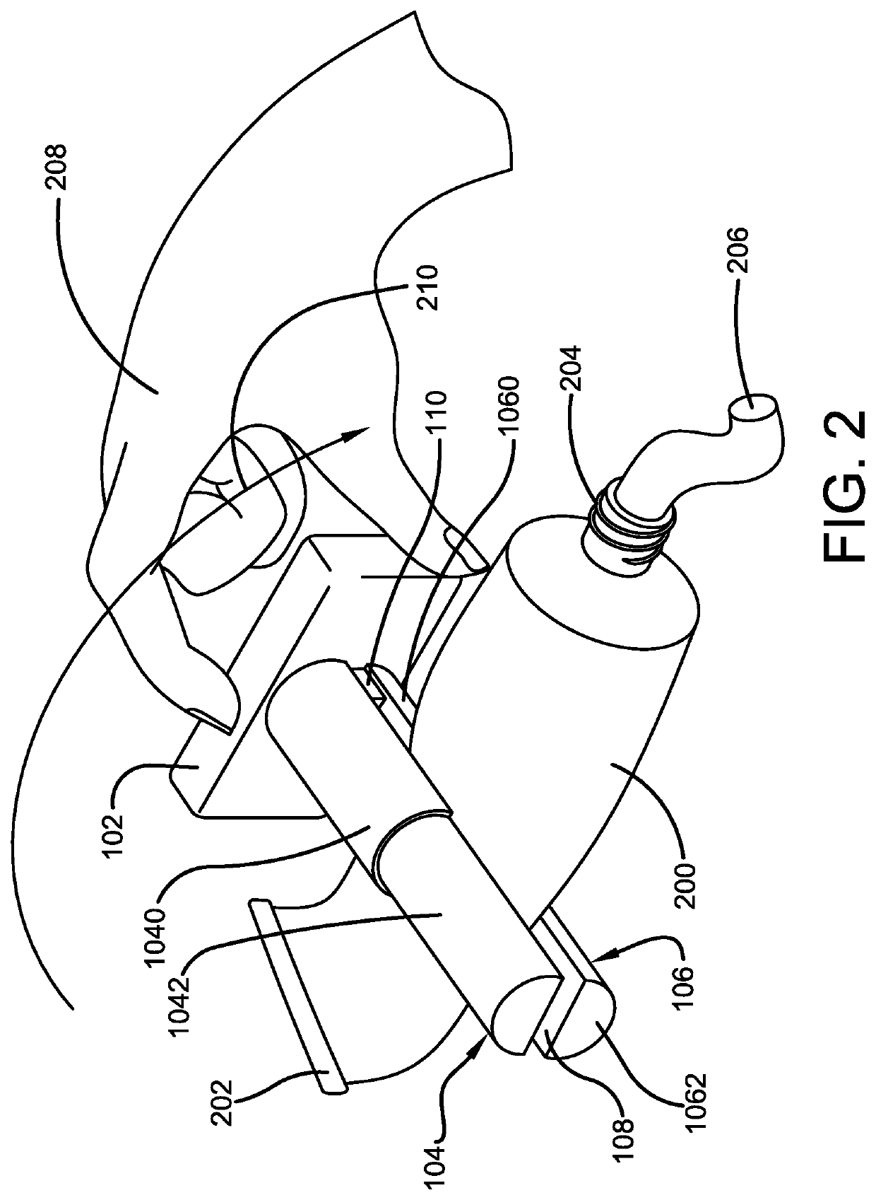
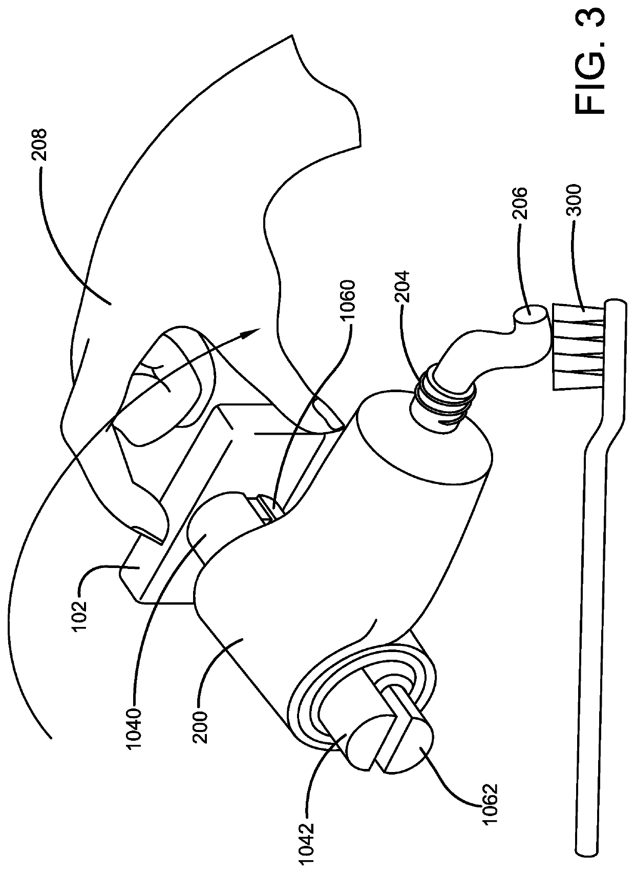
The present invention relates to a device for squeezing various types of tubes, such as paste tubes, medicine tubes, paint tubes, cosmetic tubes, adhesive tubes, and ketch-up tubes. The device includes a handle and a pair of telescoping arms that hold the tube in place and can be rotated to squeeze the contents of the tube. The device can be conveniently turned with a small or large handle and offers a simple and efficient way to remove products from flexible or collapsible tubes without any wastage. The technical effect of the device is to provide an easy and effective way to access and use the contents of various tubes.

Problems solved by technology

However, removing all liquid or paste-like contents from a tube can be difficult.
Often, material or product is left in the tube because individuals are unable to squeeze out the last remaining volume of product.
Product left in the tube is essentially wasted and ultimately leads to loss of money.
Also, children and the elderly find it extremely difficult to dispense the product from the tube when there is very little amount of product / material left inside the tube.
Children and the elderly may throw the tube away with significant unused material inside.
This leads to wastage of product and money as well.
To overcome such issues, some individuals may use excessive manual pressure throughout the tube body using both hands to evacuate the remaining product in the tube.
However, this requires a lot of manual effort, and is inconvenient to the users.

Method used


Image

  • Tube squeezing device
  • Tube squeezing device
  • Tube squeezing device

Examples


Embodiment Construction

[0021]The innovation is now described with reference to the drawings, wherein like reference numerals are used to refer to like elements throughout. In the following description, for purposes of explanation, numerous specific details are set forth in order to provide a thorough understanding thereof. It may be evident, however, that the innovation can be practiced without these specific details. In other instances, well-known structures and devices are shown in block diagram form in order to facilitate a description thereof. Various embodiments are discussed hereinafter. It should be noted that the figures are described only to facilitate the description of the embodiments. They are not intended as an exhaustive description of the invention and do not limit the scope of the invention. Additionally, an illustrated embodiment need not have all the aspects or advantages shown. Thus, in other embodiments, any of the features described herein from different embodiments may be combined.

[0...


PUM


Abstract

The present invention relates to a tube squeezing device for effectively evacuating all the material, paste, or product inside collapsible and flexible tubes. The tube squeezing device comprises a handle and clip end formed from an upper arm and a lower arm for securing the tube body. The clip end includes the upper arm and the lower arm with a slot therebetween. The tube is received in between the slot in order to urge dispensing of the material from the tube by rotating the handle to roll the arms along the tube body to push the material within the tube towards its dispensing end for easy evacuation without any wastage of product and money. The tube squeezing device is adjustable in size to accommodate tubes of different sizes and can be used by children, adults, elderly and others with compromised dexterity and strength.

Description

CROSS-REFERENCE TO RELATED APPLICATION[0001]The present application claims priority to, and the benefit of, U.S. Provisional Application No. 63 / 142,950, which was filed on Jan. 28, 2021 and is incorporated herein by reference in its entirety.FIELD OF THE INVENTION[0002]The present invention relates generally to the field of squeezing devices. More specifically, the present invention relates to a tube-squeezing device used to squeeze out the remainder of a product or material from a flexible or collapsible tube. The tube-squeezing device features a clip end having a slot to firmly secure the tube body at a closed end, and a handle to rotate the device over the secured tube body to squeeze and wind the tube body in order to push the material inside the tube toward an open end for evacuation of all the material from the tube. The invention ensures all product / material is evacuated from the tube, and that there is no waste of product. Accordingly, the present disclosure makes specific r...

Claims


Application Information

Patent Timeline
Patent Type & Authority Patents(United States)
IPC IPC(8): B65D35/32
CPCB65D35/32
Inventor BUCKLEY, WAYNE
Owner BUCKLEY WAYNE
Learn More