Electromagnetic device, method and apparatus for selective application to vertebrates

a selective application and electromagnet technology, applied in the field of manual medicine, can solve the problems of difficult control, inability to generate reproducible, and inefficient use of prior art, and achieve the effect of reducing unwanted heat, efficient generation of magnetic fields, and reducing eddy current losses

Inactive Publication Date: 2012-01-17
MURUGAN MUTHU +2
View PDF15 Cites 9 Cited by
  • Summary
  • Abstract
  • Description
  • Claims
  • Application Information

AI Technical Summary

Benefits of technology

[0007]Another very important purpose of this invention is to provide a device employing a permanent magnet to assist in the efficient electrical and mechanical propulsion of the hammer member for the effective probing and treatment of mobility issues of muscles in vertebral and extra vertebral articulations.
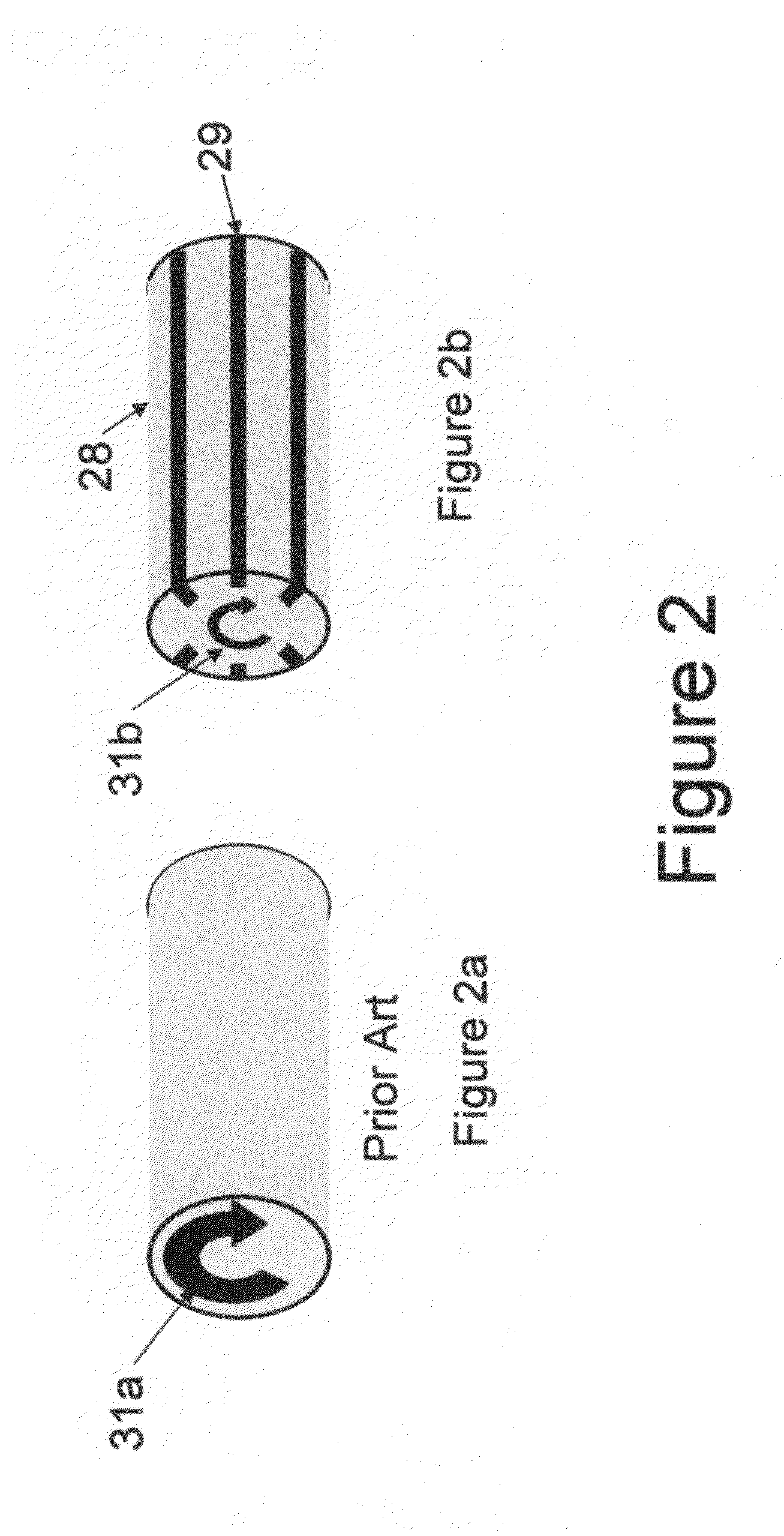
[0009]Another important purpose of this invention to provide the above referred device which includes a slotted elongated magnetizable member or core to reduce eddy current losses to thereby reduce unwanted heat.
[0010]Yet another important purpose of this invention to provide the above referred to device with an improved winding arrangement which allows for the efficient generation of a magnetic field without any substantial unwanted heat.

Problems solved by technology

Generally, the prior art can be described as inefficient to use, difficult to control and unable to generate reproducible results over a reasonable period of time.
It has found that these type of devices have serious shortcomings, as for example, they typically are electrically inefficient and generate a substantial amount of unwanted heat.
There is considerable heat generated from the electrical windings due to copper loss.
Further, their hammers are solid piece members and as such, there are substantial eddy current losses.
The overall effect of the electrical inefficiency of the prior art is above mentioned unwanted heat which is transmitted throughout the entire device reducing the device's electrical and mechanical efficiency.
Thus, the device becomes hot and difficult for the operator to hold and apply properly and are unsuitable for high frequency operation.

Method used


Image

  • Electromagnetic device, method and apparatus for selective application to vertebrates
  • Electromagnetic device, method and apparatus for selective application to vertebrates
  • Electromagnetic device, method and apparatus for selective application to vertebrates

Examples


Embodiment Construction

[0016]In describing the details of the present invention as illustrated in the several drawings, certain terminology will be utilized for the sake of clarity. The invention, however, is not to be limited to any of the specific terms used, and it is to be understood that each specific term includes reasonable equivalents which operate in a similar manner to accomplish a similar result.

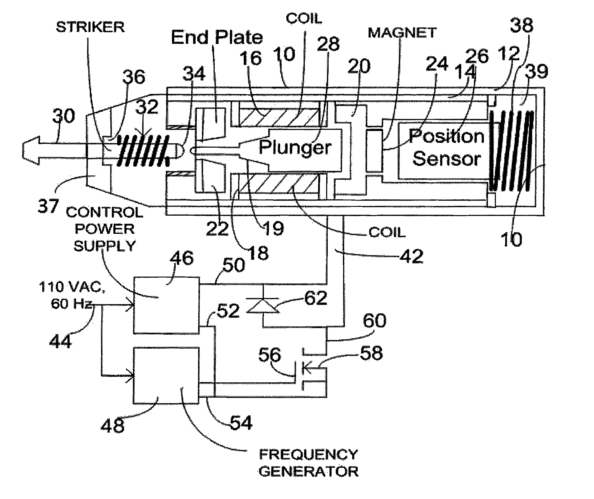
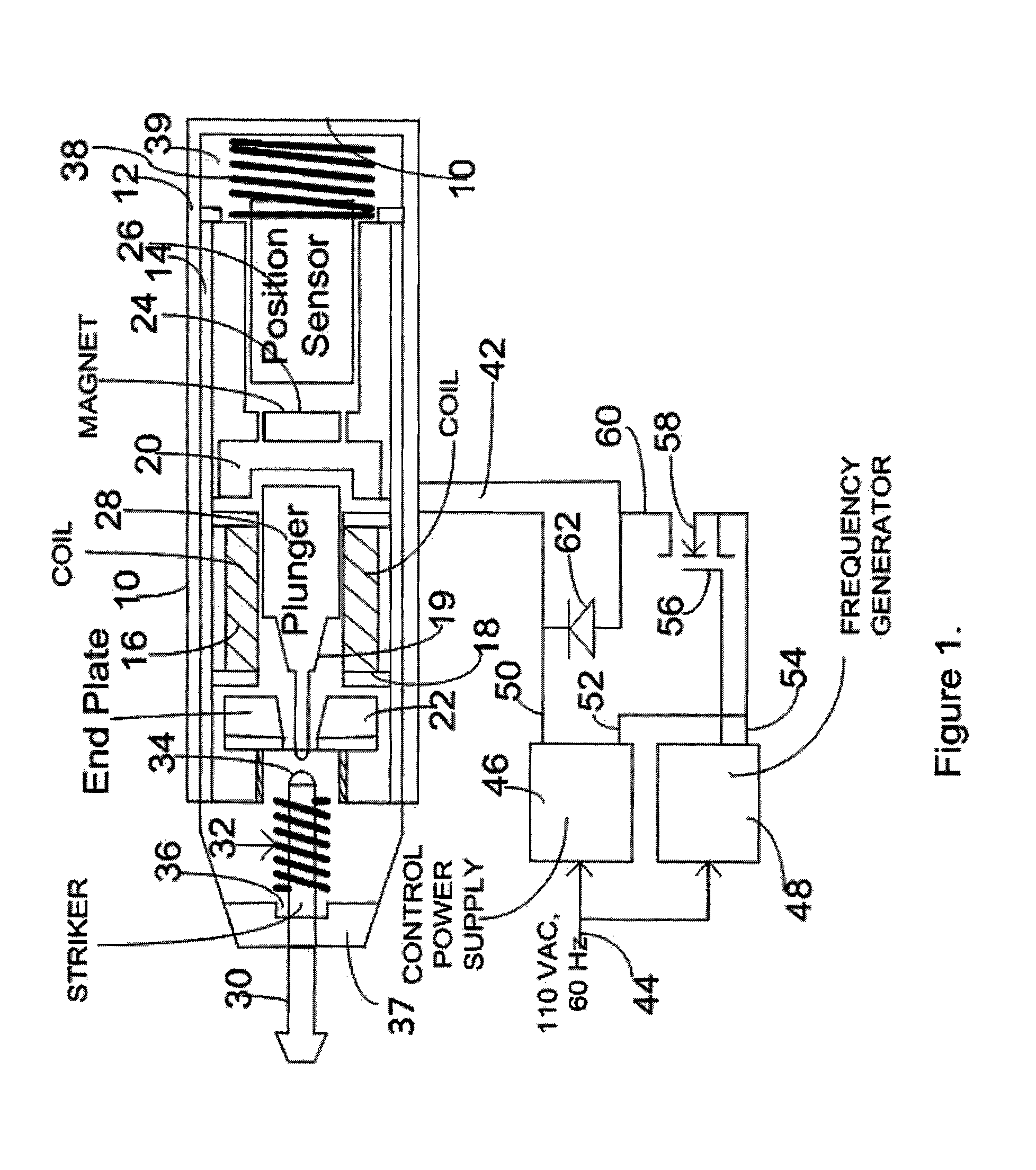
[0017]Referring the drawings, and in particular FIG. 1, there is shown and illustrated a multifunction device 10 for selective application to the body of a vertebrate which is particularly useful in the practice of manual medicine, as for example, in the chiropractic field.

[0018]The device 10 includes an outer shell or cover 12 which is typically manufactured from aluminum. The shell 12 is cylindrical in cross section but can be fashioned into a different cross section.

[0019]The outer shell 12 is slidably received by an inner shell or main housing 14 which is typically manufactured from mild steel. A el...


PUM


Abstract

A multifunction device for selective application to the body of a vertebrate is disclosed. The device includes an electromagnetic generator supported by an bobbin like member which has a bore therethrough for reciprocally receiving an elongated magnetizable member. A permanent magnet is disposed near one end of the bore. The magnetic poles of the permanent magnet are arranged to magnetically attract the elongated magnetizable member. When energized, the electromagnetic generator produces a magnetic field magnetically polarizing the elongated magnetizable member establishing a repelling magnetic force with the permanent magnet which is additive to the electromagnetic force caused by the electromagnetic generator moving the elongated magnetizable member away from the permanent magnet.

Description

BACKGROUND OF THE INVENTION[0001]The herein disclosed and claimed invention relates to a method, apparatus and device useful in the manual medicine field, as for example the chiropractic field and more particularly useful in the treatment of mobility issues in vertebral articulation.[0002]The prior art is replete with products and devices adapted to evaluate and treat issues of vertebral and extra vertebral joints. These might include manual as well as electrically controlled devices.[0003]Generally, the prior art can be described as inefficient to use, difficult to control and unable to generate reproducible results over a reasonable period of time.[0004]For example, U.S. Pat. No. 4,716,890 applies force directly to the body of the patient by pneumatic means. U.S. Pat. Nos. 4,116,235 and 4,461,286 apply force directly to the body of the patient by mechanical means by using energy stored in a spring, which energy when released by a trigger means, acts on a hammer. These types of dev...

Claims


Application Information

Patent Timeline
Patent Type & Authority Patents(United States)
IPC IPC(8): A61H1/00A61H19/00A61H23/00A61H7/00
CPCA61H1/008
Inventor MURUGAN, MUTHUFISHER, ORINALLEN, KELLY
Owner MURUGAN MUTHU
Why Eureka
Try Eureka