Ballanced rotary internal combustion engine or cycling volume machine

a rotary internal combustion engine and rotary technology, applied in the direction of rotary piston engines, rotary or oscillating piston engines, engine lubrication, etc., can solve the problems of compromising reliability, affecting the design, and unable to employ rollers at the end of sealing carriages, etc., to achieve a simplified and effective engine sealing system

Inactive Publication Date: 2005-01-06
OKULOV PAUL D
View PDF30 Cites 9 Cited by
  • Summary
  • Abstract
  • Description
  • Claims
  • Application Information

AI Technical Summary

Benefits of technology

[0029] Still, another object of the present invention is to create an effective and simplified engine sealing system.
[0030]

Problems solved by technology

These devices however, do not employ rollers at the end of sealing carriages, save for U.S. Pat. No. 3,387,596, by Niemand where rollers are used in combination with a cam surface for deformation of the shape of a four blade parallelogram.
These arrangements are useful, however a common disadvantage exists in that the pivoting blades or links arranged in such configurations are extremely difficult to seal at the pivoting ends.
Several different types of seals are needed to provide adequate sealing of the device similar to U.S. Pat. No. 6,164,263, which greatly complicates the design and compromises reliability.
In addition, the complicated shape of the parts and greater surface area of the combustion chamber both determine high thermal losses and lower efficiency for this type of engine.
The disadvantage of the configuration is that the combustion chamber has a very high surface to volume ratio, which leads to thermal inefficiency.
Also, the unbalanced lateral forces applied against the cylindrical stator create friction losses and excessive wear of apex seals (FIG. 10) followed by widening of the tolerance gap between levers.
This compromises the performance of the already complicated sealing system, reduces the torque and increases complexity of the design.
Disadvan

Method used


Image

  • Ballanced rotary internal combustion engine or cycling volume machine
  • Ballanced rotary internal combustion engine or cycling volume machine
  • Ballanced rotary internal combustion engine or cycling volume machine

Examples


Embodiment Construction

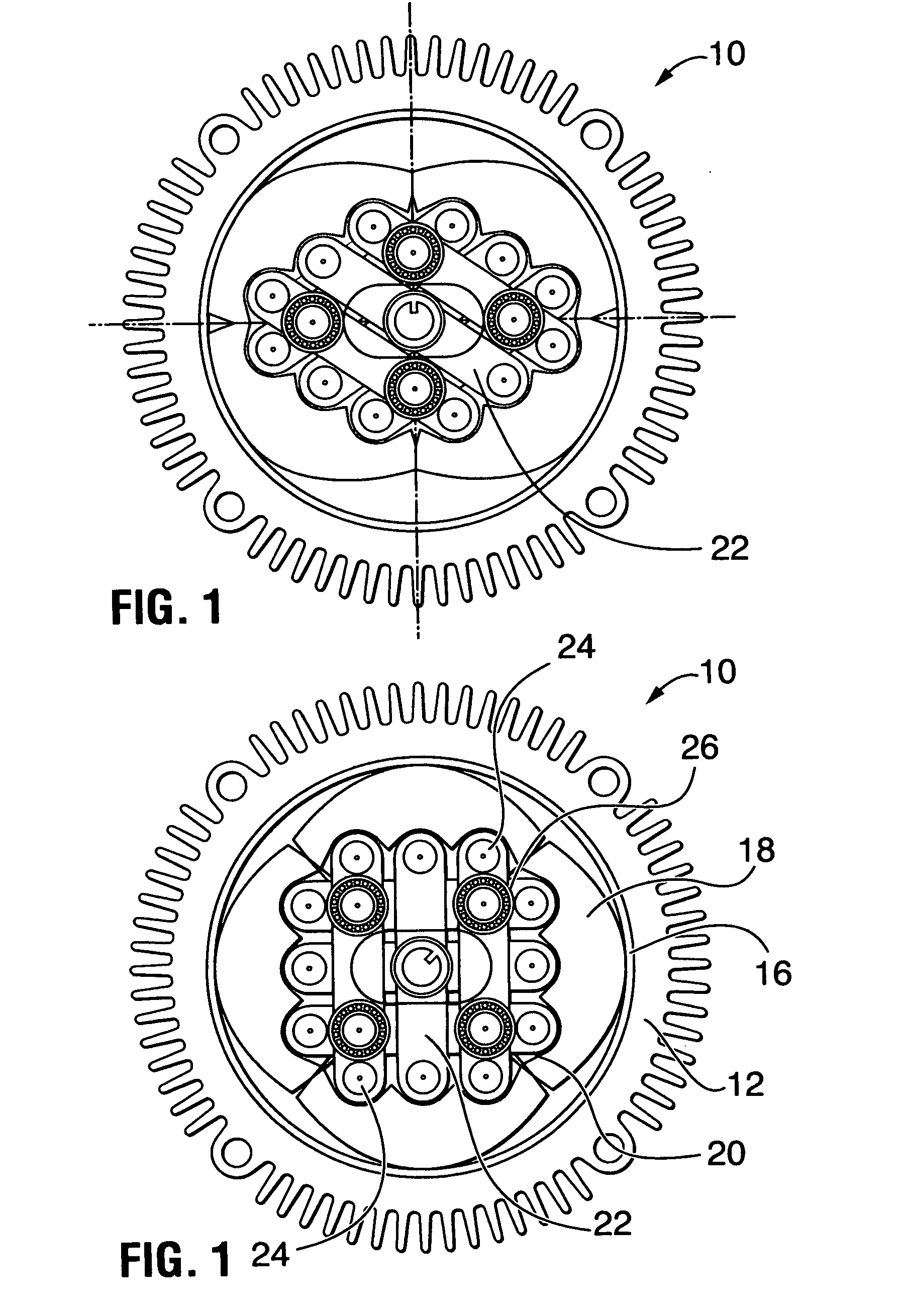
[0109]FIG. 1 illustrates a cross-sectional view of the rotary apparatus, generally denoted by numeral 10. FIGS. 11 and 12 illustrate a side and partially cutaway view of the arrangement 10, respectively. With respect to FIGS. 1, 11 and 12, the arrangement 10 provides a housing 12 having end covers 14 within which is disposed a stator 16. The stator is shown in the example as a circular arrangement; however, the arrangement may also be of a semi-circular shape or have an adjustable liner to be discussed hereinafter.

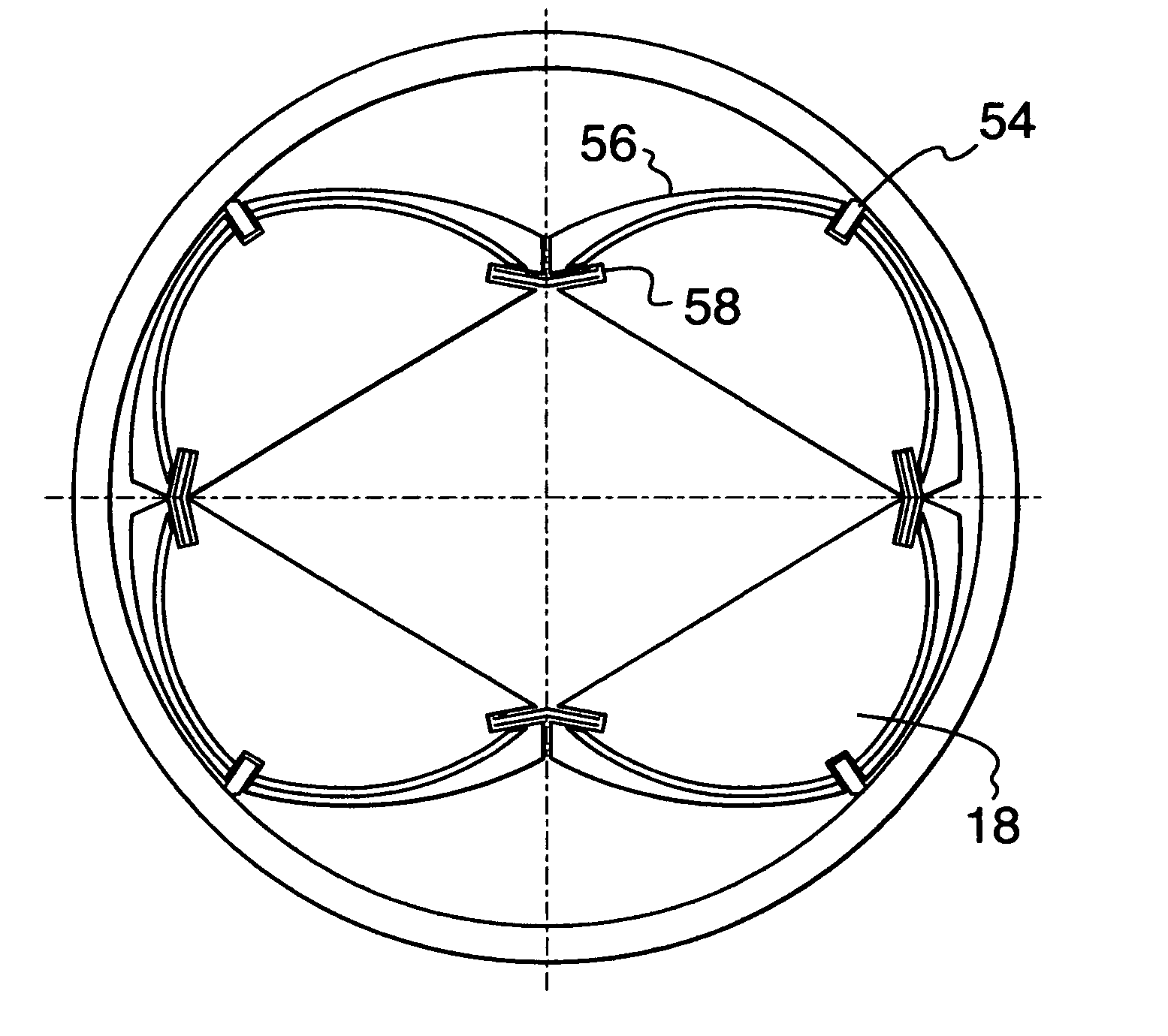
[0110] Disposed within the housing 12 is a plurality of pistons 18, shown in the example in a quantity of four. As is illustrated, the pistons 18 have a general arc shape for contact with the stator 16. The internal area of the pistons includes a plurality of generally rounded or scalloped portions 20. The scalloped portions are configured to permit general movement of linkages 22.

[0111] As illustrated, diametrically opposed pairings of pistons 18 are connected by linkag...


PUM


Abstract

A balanced rotary cycling machine suitable for use as an internal combustion engine, compressed gas or steam engine, compressor or pump is disclosed herein. The rotor assembly consists of four articulating pistons where the opposite pistons are inter-linked with each other by pivoted rods comprising a parallelogram mechanism and therefore eliminating a need for pivots between pistons. The rotor assembly rotates inside or outside of a circular or non-circular stator depending on the configuration chosen. A variety of mechanisms for shape deformation of four piston assembly during its rotating cycle is also disclosed herein, as well as detailed descriptions of preferred embodiments, including a four cycle internal combustion engine with circular stator, marine engine with polymer parts and a four cycle automobile rotary engine with conventional oil pan. In addition, a method of operation of external rotary combustion engine, employing a high-pressure compressor and an external combustion chamber, is disclosed. This invention also teaches a novel lubrication system for rotary engine providing low emissions. The engine has few moving parts, simplified circular or semi-circular stator shape and utilizes simple and effective sealing techniques. It is fully balanced, has very low friction and heat losses and can employ a pre-designed configuration of the combustion chamber for a desired compression ratio and power output.

Description

FIELD OF THE INVENTION [0001] This application is a continuation in part of U.S. patent application Ser. No. 10 / 160,072, filed Jun. 4, 2002, which claims priority from U.S. Provisional Application No. 60 / 295,577, filed Jun. 5, 2001. BACKGROUND OF THE INVENTION [0002] Variable shape rotors are known from the prior art, as an example of which was provided by Werner in (U.S. Pat. No. 716,970). Another type of engine was disclosed by Wankel, who established a rotary engine with a fixed shape rotor and epitrochoidal shape stator. [0003] In present invention, during the rotation cycle, the rotor pivoting blades or pistons align alternatively in a lozenge and a square configuration so that the volume between the blades itself, side walls and the stator (contour wall) changes, and in so doing, allows to create a cycling machine. [0004] Rotary engines and cycling machines based on the principle set forth in Edward H. Werner's invention of 1902 (U.S. Pat. No. 716,970) and further inventions d...

Claims


Application Information

Patent Timeline
IPC IPC(8): F01C1/00F01C1/10F01C1/22F01C1/34F01C1/40F01C5/04F01C19/00F01C19/02F01C21/00F01C21/08F01C21/10F02B53/00F02B75/36F04C27/00
CPCF01C1/10Y02T10/17F01C1/34F01C1/40F01C19/02F01C21/0809F01C21/0836F01C21/10F02B53/00F02B57/00F02B75/36F02B2053/005F04C27/001F04C2250/301F01C1/22Y02T10/12
Inventor OKULOV, PAUL D.
Owner OKULOV PAUL D
Why Eureka
Try Eureka