Demand gas flow valve apparatus

a demand gas and valve technology, applied in the field of demand gas flow valve apparatus, can solve the problems of inability to reasonably avoid the build-up of exhaled nsub>2/sub>o waste gas in the hospital environment using such “dental equipment”, and the demand valve, a relatively delicate mechanism, is susceptible to being damaged, etc., and achieves the effect of simple and effectiv

Active Publication Date: 2021-09-07
SEDATION SYST LLC
View PDF37 Cites 0 Cited by
  • Summary
  • Abstract
  • Description
  • Claims
  • Application Information

AI Technical Summary

Benefits of technology

[0035]Through the foregoing “demand” gas flow valve, it is thus an object of the claimed subject matter to provide a simplified and effective means for enabling a patient to self-administer gas, or mixtures of same, through a face mask and breathing circuit. Preferably, though not exclusively, the claimed subject matter advantageously may be employed to administer sedation gas to patients, including but not limited to, mixtures of nitrous oxide and oxygen.

Problems solved by technology

A full face-mask, therefore, cannot be used in dentistry for such application.
Accordingly, unless provision is made to collect or otherwise scavenge the breath of a patient exhaled through the mouth, build-up of exhaled N2O waste gas in the hospital environment using such “dental equipment” cannot reasonably be avoided.
Additionally, because the patient must manually grasp the relatively bulky mask and demand valve assembly during gas administration, the demand valve, a relatively delicate mechanism, is susceptible to being damaged by being dropped or otherwise mishandled by the patient.
Moreover, the scavenger or surge tank is of fixed volume and can be overwhelmed by vigorous exhalation causing venting and possible room contamination.
Also, the surge tank tends to collect moisture which compromises its function and tends to promote growth of bacteria or other contagions.
Finally, the surge tank includes a hydrophobic polyurethane resistance plug which may increase the difficulty of exhalation experienced by the patient.
Furthermore, where a definition or use of a term in a reference, which is incorporated by reference herein, is inconsistent or contrary to the definition of that term provided herein, the definition of that term provided herein applies and the definition of that term in the reference does not apply.

Method used


Image

  • Demand gas flow valve apparatus
  • Demand gas flow valve apparatus
  • Demand gas flow valve apparatus

Examples


example

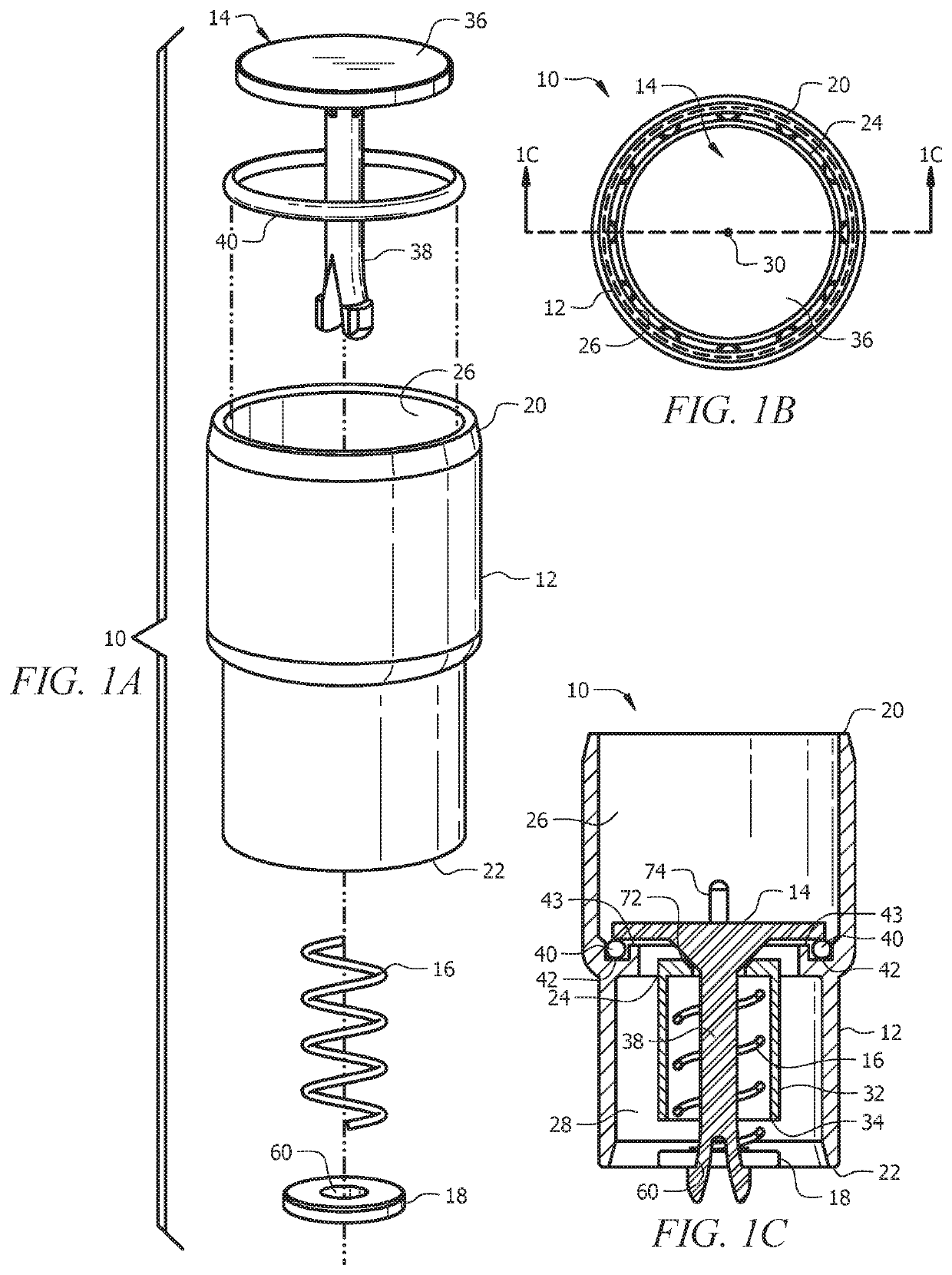
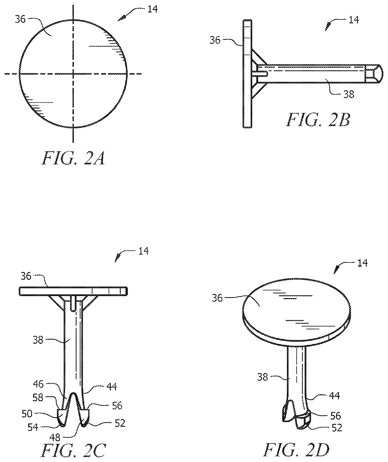
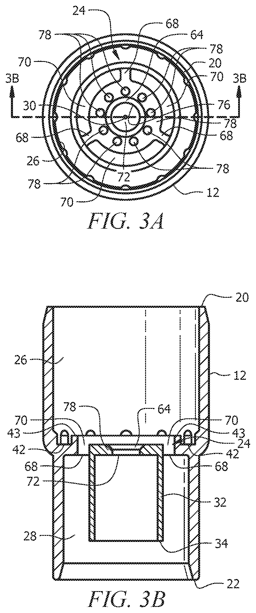
[0082]Without limiting the claimed subject matter, and merely for the sake of illustration, an example of demand gas valve apparatus 10 according to an embodiment of the claimed subject matter suitable for use in supplying medical gas to an “average adult” was constructed using conventional stereo-lithography (SLA) techniques having the following dimensions:[0083]Length (axial extent): 39.69 mm (1.563 in.)[0084]Inside diameter of first end: 22 mm (0.866 in)[0085]Outside diameter of first end: 25.05 mm (0.096 in)[0086]Outside diameter of second end: 22 mm (0.866 in)[0087]Inside diameter of second end: 18.95 mm (0.746 in)[0088]Wall thickness: 1.525 mm (0.059 in)[0089]Valve disc diameter: 19.69 mm (0.775 in)[0090]Thickness of valve disc: 1.524 mm (0.06 in)[0091]Stem length: 24.09 mm (0.948 in)[0092]Stem diameter: 3.302 mm (0.13 in)[0093]Sleeve length: 13.208 mm (0.52 in)[0094]Sleeve diameter: 11.049 mm OD×9.525 mm ID (0.435 in OD×0.375 in ID)[0095]Retainer washer diameter: 11.049 mm OD...


PUM


Abstract

A breathing circuit system for delivering gas from a fresh source to a user through a face mask. The system includes a cylindrical housing and a resiliently-biased valve supported substantially centrally within the housing. In the default or “off” position, the resilient bias causes the valve to be seated on a valve seat shutting off axial flow of gas through the valve housing. When the patient or user breathes, negative pressure is applied to one side of the valve effective to sufficiently overcome the resilient bias imposed on the valve to move the valve off the valve seat axially (or otherwise open in another direction) within the housing, thereby allowing flow of gas through both the valve seat and the valve housing, and into the breathing circuit connected thereto. When the patient's breathing pauses and begins to exhale, the valve bias returns the valve to its default or off condition shutting off flow of gas through the valve.

Description

CROSS-REFERENCE TO RELATED APPLICATIONS[0001]This nonprovisional application is a divisional of and claims priority to currently pending U.S. Nonprovisional patent application Ser. No. 14 / 843,500, entitled “Demand Gas Flow Valve Apparatus,” filed Sep. 2, 2015 by the same inventor, which is a continuation of and claims priority to U.S. Provisional Patent Application No. 62 / 070,670, entitled “Demand Gas Flow Valve Apparatus,” filed Sep. 2, 2014 by the same inventor, and is a continuation-in-part of and claims priority to U.S. Nonprovisional patent application Ser. No. 14 / 479,843, entitled “Respiratory Face Mask and Breathing Circuit Assembly,” filed Sep. 8, 2014 by the same inventor, which is a continuation of and claims priority to U.S. Nonprovisional patent application Ser. No. 12 / 658,019, entitled “Respiratory Face Mask and Breathing Circuit Assembly,” filed Feb. 1, 2010 by the same inventor, now U.S. Pat. No. 8,826,905, all of which are incorporated herein by reference in their en...

Claims


Application Information

Patent Timeline
Patent Type & Authority Patents(United States)
IPC IPC(8): A61M16/20A61M16/10A61M16/08A61M16/00A61M16/06A61M16/12
CPCA61M16/208A61M16/0003A61M16/06A61M16/0891A61M16/104A61M16/122A61M2016/003A61M2016/0027A61M2202/0208A61M2202/0283A61M2205/3334A61M16/0075A61M16/009A61M2016/0039A61M2202/0007
Inventor NASHED, RAMSES
Owner SEDATION SYST LLC
Why Eureka
Try Eureka