
System for additive manufacturing

a technology of additive manufacturing and system, applied in the direction of additive manufacturing, 3d object support structure, application of layer means, etc., can solve the problems of model material within the feed channel of the printhead may decay, risk of decomposition or disintegration, formation of solid particles of disintegrated modeling material,

Active Publication Date: 2021-11-09
BOND HIGH PERFORMANCE 3D TECH BV
View PDF7 Cites 2 Cited by
  • Summary
  • Abstract
  • Description
  • Claims
  • Application Information

AI Technical Summary

Benefits of technology

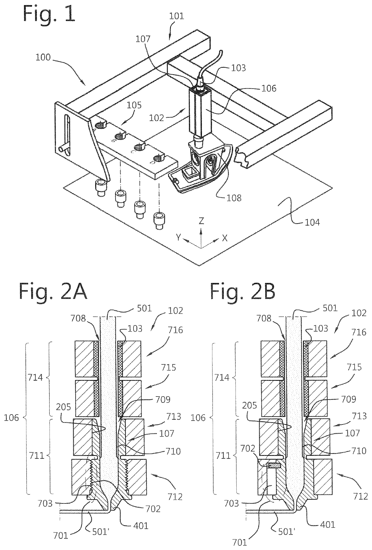
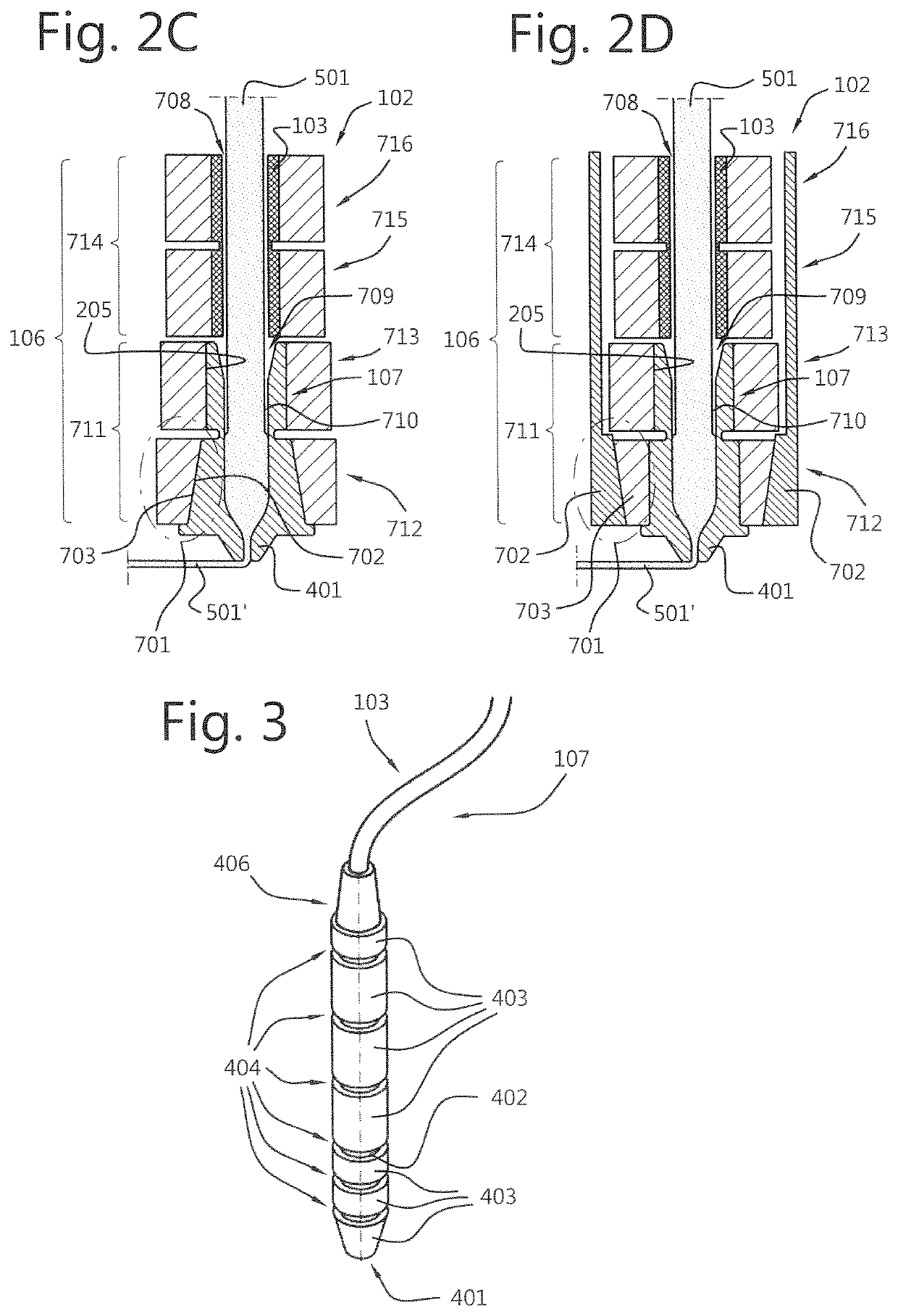
The invention is a system for automating the replacement of a used feedstock liquefying unit in a printer with a new unit. The system makes use of a connection arrangement with heat exchanging means that remains unchanged during the exchange of the feedstock liquefying unit. The heat exchanging means stays connected to its energy source that is configured and arranged to heat the feedstock liquefying unit, resulting in a more reliable and faster way of exchanging the unit. The system also includes a thermally conductive tube that has at least one concentric heat conductive section and the heat conductive elements of the heat exchanging sections are mutually thermally insulated, allowing for independent control of temperature zones and the prevention of thermal crosstalk. This enables the feedstock material to be heated in stages.

Problems solved by technology

The modeling material within the feed channel of the printhead may decay while printing.
For fusible material which is melted prior to deposition by the feedstock liquefying unit of a printhead, in order for it to be printable, there is a risk of decomposition or disintegration if the material is kept at a high temperature near the melting temperature too long.
This may give rise to formation of solid particles of disintegrated modeling material.
In depositing for example curable resins, also contaminants within the modeling material, and / or dead spots within the feed channel may eventually give rise to formation of solid particles.
As a consequence, undesired solidification and disintegration is usually initiated in this region.
While depositing the modeling material, debris or solid particles in the feed channel or nozzle of the feedstock liquefying unit may cause clogging and can lead to reflow of material inside the feedstock liquefying unit, causing jamming of the feedstock liquefying unit.
Alternatively, the nozzle opening of the feedstock liquefying unit can wear out and dilate, resulting in a larger width of printed tracks and less accurate part dimensions.
Moreover, the pressure of the extruded material from the nozzle will be higher, potentially resulting in over-extrusion of the layer being deposited on the previous layer.
This may result in excessive forces between the object and the printhead and in a rough surface of the created object due to overflow of the modeling material.
The overflow of modeling material may further lead to debris or residue on the outside of the nozzle tip of the printhead which may come off the nozzle tip and fuse with the object being printed and cause potential loss of the object.
This procedure however causes interruption of the 3D modeling process wherein the printhead needs to be cooled down.
The interruption and subsequent cooling down may lead to abortion of an ongoing modeling job and subsequent loss of resources and time.
As printheads may be bulky, considerably large sized and relatively expensive holders or cassettes are needed for storing the printheads.

Method used


Image

  • System for additive manufacturing
  • System for additive manufacturing
  • System for additive manufacturing

Examples


first embodiment

[0093]FIG. 6A shows a schematic longitudinal sectional view of a first exemplary, non-limiting embodiment of an actuating means 604 that is arranged in contact with a first exemplary, non-limiting embodiment of a nozzle 401 of a feedstock liquefying unit 107 according to a first exemplary, non-limiting embodiment thereof. FIG. 6B shows a schematic cross-sectional view of the first exemplary, non-limiting embodiment of the actuating means 604 shown in FIG. 6A. In FIG. 6B it is shown that the actuating means 604 comprises an engagement arrangement 717 having a hexagonal shaped receiving space. The person skilled in the art will appreciate that any polygonal shape with any arbitrary number of sides can be used as long as the required torque can be achieved that is required to exchange the feedstock liquefying unit 107. In this exemplary embodiment the engagement arrangement 717 is configured and arranged to engage with the nozzle 401 of the feedstock liquefying unit 107 that is accomm...

second embodiment

[0094]FIG. 6C shows a schematic longitudinal sectional view of a second exemplary, non-limiting embodiment of the actuating means 604 that is arranged in contact with a second exemplary, non-limiting embodiment of the nozzle 401 of the feedstock liquefying unit 107 according to the first exemplary, non-limiting embodiment thereof. FIG. 6D shows a schematic cross-sectional view of the second exemplary, non-limiting embodiment of the actuating means 604 shown in FIG. 6C. In FIG. 6D it is shown that the actuating means 604 comprises an engagement arrangement 717 having a star shaped receiving space. The person skilled in the art will appreciate that any star shape with any arbitrary number of sides can be used as long as the required torque can be achieved that is required to exchange the feedstock liquefying unit 107. In this exemplary embodiment the engagement arrangement 717 is configured and arranged to engage with the nozzle 401 of the feedstock liquefying unit 107 that is accomm...

third embodiment

[0095]FIG. 6E shows a schematic longitudinal sectional view of a third exemplary, non-limiting embodiment of the actuating means 604 that is arranged in contact with a third exemplary, non-limiting embodiment of the nozzle 401 of the feedstock liquefying unit 107 according to a second exemplary, non-limiting embodiment thereof. FIG. 6F shows a schematic cross-sectional view of the third exemplary, non-limiting embodiment of the actuating means 604 shown in FIG. 6E. In FIG. 6F it is shown that the actuating means 604 is a wrench that comprises an engagement arrangement 717 that is provided with two recesses 606 that are configured and arranged to engage with two pins 405 of the feedstock liquefying unit 107 to enable exchange of the feedstock liquefying unit upon rotation of the actuating means 604 relative to the feedstock liquefying unit 107. The person skilled in the art will appreciate that any number of recesses and pins can be used as long as the required torque can be achieve...


PUM

PropertyMeasurementUnit
fused deposition modelingaaaaaaaaaa
thermally conductiveaaaaaaaaaa
heat conductiveaaaaaaaaaa

Abstract

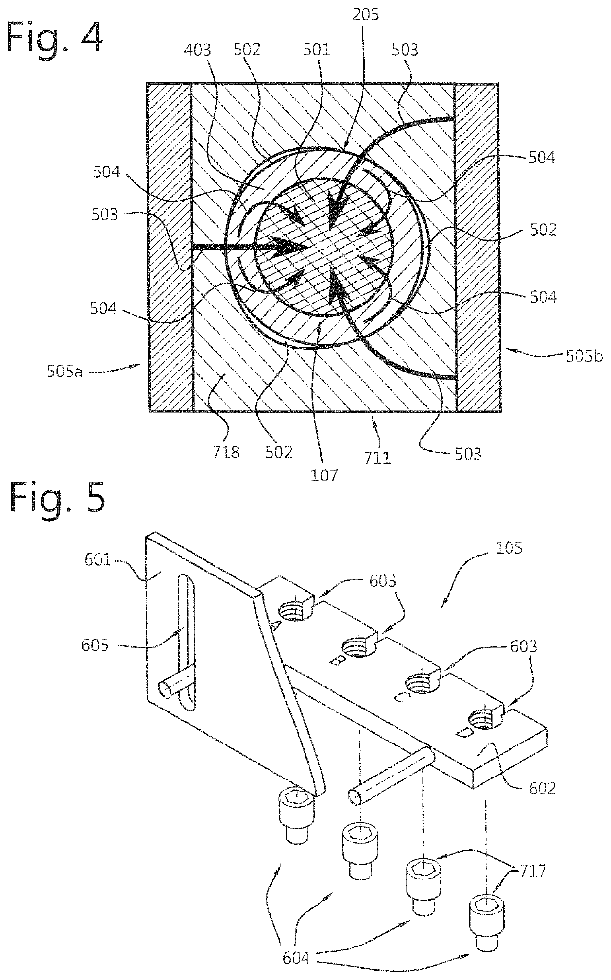
A system for additive manufacturing, having at least one printhead assembly that includes a feedstock liquefying unit for liquefying and depositing feedstock material via a nozzle, heat exchanging elements attached to the printhead assembly being provided with a receiving space that is configured and arranged to receive the feedstock liquefying unit, and a connection arrangement that includes a first connecting element and a second connecting element that are configured and arranged to one of establish a releasable connection with each other and disconnect the releasable connection upon rotating the first and second connecting elements with respect to each other. The system further including a feedstock liquefying unit storage, having an actuating device that enables assembling and disassembling the connecting arrangement to automatically exchange the feedstock liquefying unit, and a controller for controlling automatic exchange of the feedstock liquefying unit.

Description

FIELD OF THE INVENTION[0001]The present invention relates to a system for additive manufacturing (AM) of a three-dimensional (3D) object using 3D printing. More specifically the invention relates to replacement of a feedstock liquefying unit in such a system.BACKGROUND OF THE INVENTION[0002]In three-dimensional modeling, objects are formed by layering modeling material in a controlled manner such that a desired three dimensionally shaped object can be created. This way of forming objects can also be referred to as additive manufacturing (AM). Very often for three-dimensional modeling a three-dimensional modeling printer is used. The printer has a three dimensionally moveable printhead which dispenses the modeling material, while the printhead is moved over previously deposited tracks of the modeling material.[0003]The object to be printed can be placed on a build plate. The printhead is movable in a three dimensional space relative to the object being modeled or printed. In some cas...

Claims


Application Information

Patent Timeline
Patent Type & Authority Patents(United States)
IPC IPC(8): B29C64/209B33Y30/00B33Y40/00B33Y50/02B29C64/321B29C64/393
CPCB29C64/209B29C64/321B29C64/393B33Y30/00B33Y40/00B33Y50/02B29C64/118B29C64/20
Inventor BRUGGEMAN, THOMAS JONATHANBRUGGEMAN, ADRIANUSVOSS, KEVIN HENDRIK JOZEFGROEN, KLAASTIMMER ARENDS, JOHANNES HERMANNUSWOLBERS, MARTIJN JOHANNESKUIT, KOENDERT HENDRIKSPEELMAN, MARALD
Owner BOND HIGH PERFORMANCE 3D TECH BV
Learn More