Very high temperature electrical winding

a technology of electrical winding and high temperature, which is applied in the direction of windings, dynamo-electric components, dynamo-electric machines, etc., can solve the problems of difficult thermal management of electrical conductors, high manufacturing costs, and inconvenient turning of insulation materials, so as to reduce wear and easy sealing

Active Publication Date: 2019-12-31
CORETEQ SYST
View PDF46 Cites 0 Cited by
  • Summary
  • Abstract
  • Description
  • Claims
  • Application Information

AI Technical Summary

Benefits of technology

[0009]This allows the windings to be conveniently turned on the armature in a precise manner, since each conductor position is accurately constrained by the components. There is little of no movement, so wear is reduced. The arrangement is very easy to seal. Ceramic in particular is very suitable as a material, as it has excellent temperature resistance and is hard wearing and resistant to abrasion.

Problems solved by technology

The use high temperature polymeric insulation material would enable the electrical machines to have a maximum operating temperature of the order of 250 C. However, it is believed that even this stable, oxidation resistant, polymeric insulation material will not have a maximum operating temperature above 300 C.
However, this is not desirable because the inorganic insulation material tends to be bulky, limiting the packing density of the electrical conductor, and the electrical conductors also require potting in an inorganic cement, and in addition the manufacturing process is very labour intensive.
The use of an inorganic insulation material may be based on ceramic cloth and inorganic cement, however this is not desirable because these inorganic insulation materials have poor thermal conductivity and would make the thermal management of the electrical conductor difficult.
The presence of moisture tends to degrade the electrical insulation by allowing leakage currents to earth or between turns of the electrical conductor.
The presence of oil tends to degrade the electrical insulation by forming carbon also allowing leakage currents to earth or between turns of the electrical conductor.
Also the thermal expansion mismatch may cause damage to the insulation material during thermal cycling of the electrical conductor.

Method used


Image

  • Very high temperature electrical winding
  • Very high temperature electrical winding
  • Very high temperature electrical winding

Examples


Embodiment Construction

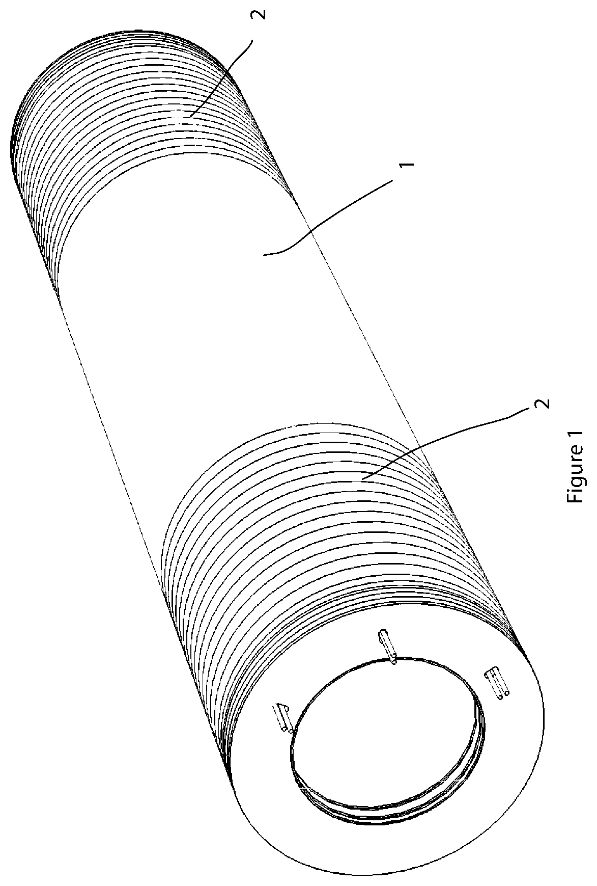
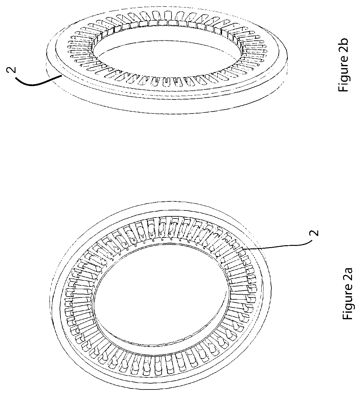
[0037]Referring to FIG. 1 there is shown a stator construction consisting of a stack of motor laminations 1 with two stacks of ceramic insulated end turn laminations 2 located at both ends of the series conventional laminations 1.

[0038]Referring to FIG. 6, the motor laminations 1 are of a generally conventional one-piece arrangement, made for example from sheet steel, having an outer circumferential yoke 17, with radially extending teeth 18. In this embodiment, rather than conventional discreet tooth lips, the tooth lips meet to form a continuous inner annular barrier 19.

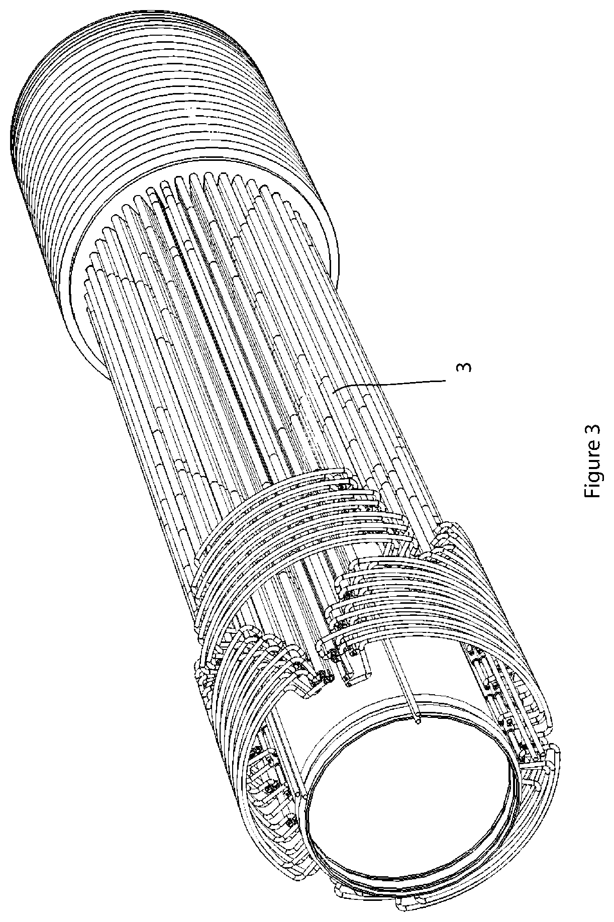
[0039]The conductors of the windings are then disposed in slots 6 and insulated in various ways. Referring to FIG. 3, each conductor is threaded through a ceramic tube 3, and each ceramic tube is inserted into the slots 6 of FIG. 6.

[0040]Alternatively, the ceramic tube may be formed of separate pieces. Referring to FIGS. 8 and 9, conductors 25 may be threaded through or encased in two part interlocking ceramic extru...


PUM


Abstract

A stator has a field winding, the winding comprising a plurality of axial conductors connected at their ends to form at least one circuit with a number of turns. Each axial conductor, or set of axial conductors having a common voltage, is disposed within an insulated channel member, the insulated channel member being disposed within a stack of laminations. The axial conductors and the tubular insulation members are radially distributed at equal angles.

Description

CROSS-REFERENCE TO RELATED APPLICATIONS[0001]This application is a National Stage Entry of PCT / EP2014 / 074798, and claims priority to, and the benefit of, Great Britain Patent Application No. GB 1320245.2, filed Nov. 15, 2013, the entirety of which is hereby incorporated by reference as if fully set forth herein.[0002]At the present electrical machines comprise one or more electrical conductor windings each of which has a polymeric insulation material. These electrical machines have a maximum operating temperature of the order of 200 C due to the polymeric insulation material applied to the electrical conductor windings.[0003]The use high temperature polymeric insulation material would enable the electrical machines to have a maximum operating temperature of the order of 250 C. However, it is believed that even this stable, oxidation resistant, polymeric insulation material will not have a maximum operating temperature above 300 C.[0004]There is a requirement for electrical machines ...

Claims


Application Information

Patent Timeline
Patent Type & Authority Patents(United States)
IPC IPC(8): H02K3/30H02K3/34
CPCH02K3/345H02K3/30H02K15/0068
Inventor HEAD, PHILIPMANSIR, HASSAN
Owner CORETEQ SYST
Why Eureka
Try Eureka