Magnetic field sensor with suspended stress gauge

a stress gauge and magnetic field technology, applied in the field of magnetic field sensors, can solve the problems of high energy consumption of other types of sensors, inability to adapt to perform certain magnetic field measurements, and the production of such sensors becomes much more complex. , to achieve the effect of strong magnetic sensitivity

Active Publication Date: 2014-09-30
COMMISSARIAT A LENERGIE ATOMIQUE ET AUX ENERGIES ALTERNATIVES
View PDF15 Cites 11 Cited by
  • Summary
  • Abstract
  • Description
  • Claims
  • Application Information

AI Technical Summary

Benefits of technology

[0009]One aim of the present invention is therefore to propose a highly-integrated and compact magnetic field sensor that can be made entirely using microsystem or nanosystem technology, i.e. of the MEMS or NEMS types, allowing single-axis or multi-axis magnetic field detection, not very sensitive to accelerations and with strong magnetic sensitivity.

Problems solved by technology

One of the problems frequently encountered concerns the production of a sensor able to perform a magnetic field measurement along several axes.
But when one wishes also to measure the vertical component of the magnetic field (component perpendicular to the plane of the sensor), the production of such a sensor becomes much more complex, in particular if one wishes for this sensor also to measure magnetic components of the magnetic field located in the plane of the sensor.
Moreover, certain types of sensors are not adapted to perform certain magnetic field measurements.
Other types of sensors also have substantial electricity consumption, such as AMR and fluxgate sensors for example, which can be a drawback, for example when these sensors are intended to be used in onboard applications.
Furthermore, their operation in resonant mode requires substantial quality factors that can only be obtained through costly vacuum packaging.
However, existing magnetic material sensors have other major drawbacks: detection according to only 1 or 2 axes, non-integrated sensor, excessive sensitivity to accelerations, or excessively low magnetic field detection sensitivity.

Method used


Image

  • Magnetic field sensor with suspended stress gauge
  • Magnetic field sensor with suspended stress gauge
  • Magnetic field sensor with suspended stress gauge

Examples


first embodiment

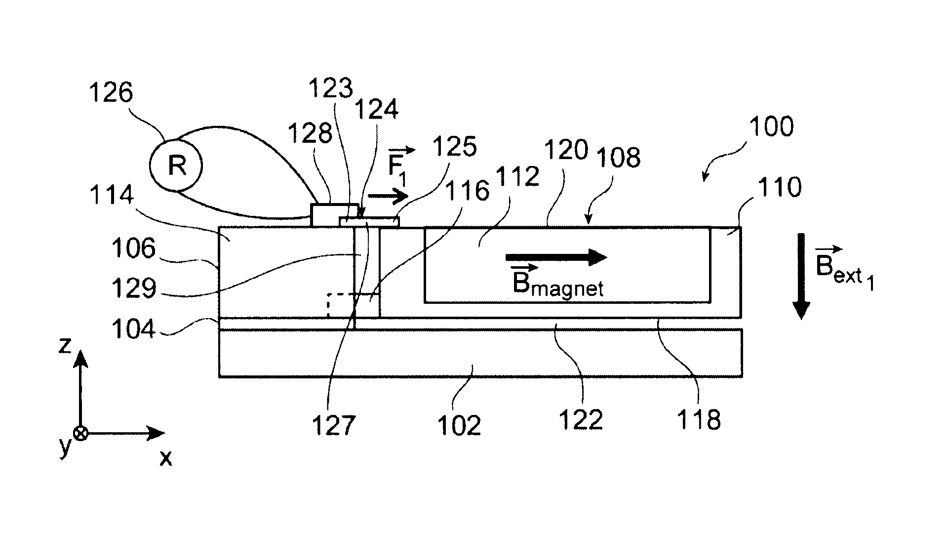
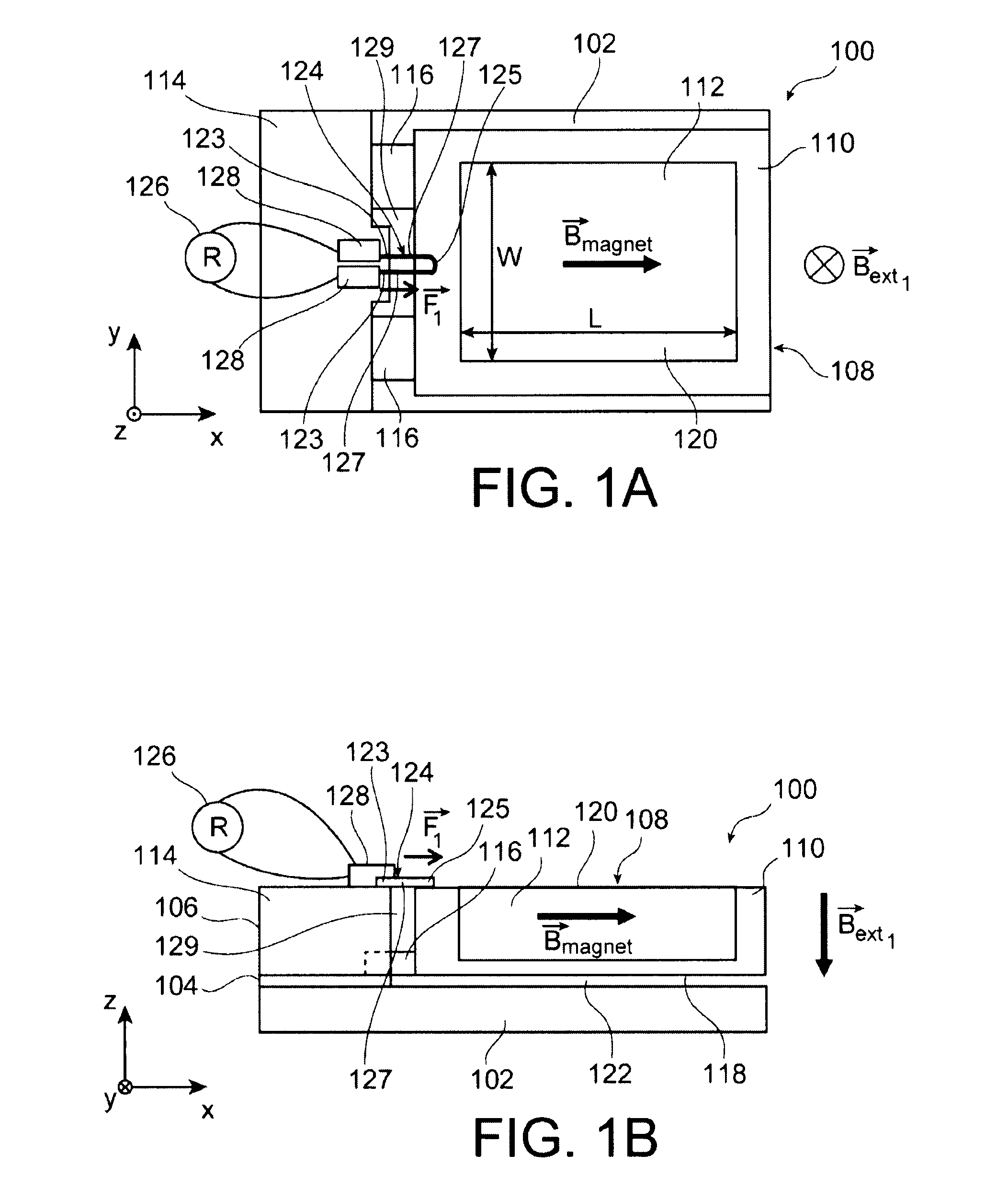
[0084]One example of a magnetic field sensor 100 will be described in connection with FIGS. 1A and 1B, which respectively show a top view and a profile view of the sensor 100.

[0085]The sensor 100 is made from a SOI substrate having a stack formed by a support layer 102 composed of semiconductor, a dielectric layer 104 and a superficial layer 106 also composed of semiconductor. The semiconductor of the layers 102 and 106 is for example monocrystalline or polycrystalline silicon. The superficial layer 106 could also be composed of SiGe or any other material of III-V type. The dielectric layer 104 is for example composed of SiO2. In one alternative, the sensor 100 could be made from another type of substrate (bulk, semiconductor on glass, . . . ).

[0086]The sensor 100 has a body 108 forming a mobile portion of the sensor 100 and comprising magnetic means able to move the body 108 by the action of a magnetic field. In this first embodiment, the body 108 has a box 110 formed in the super...

second embodiment

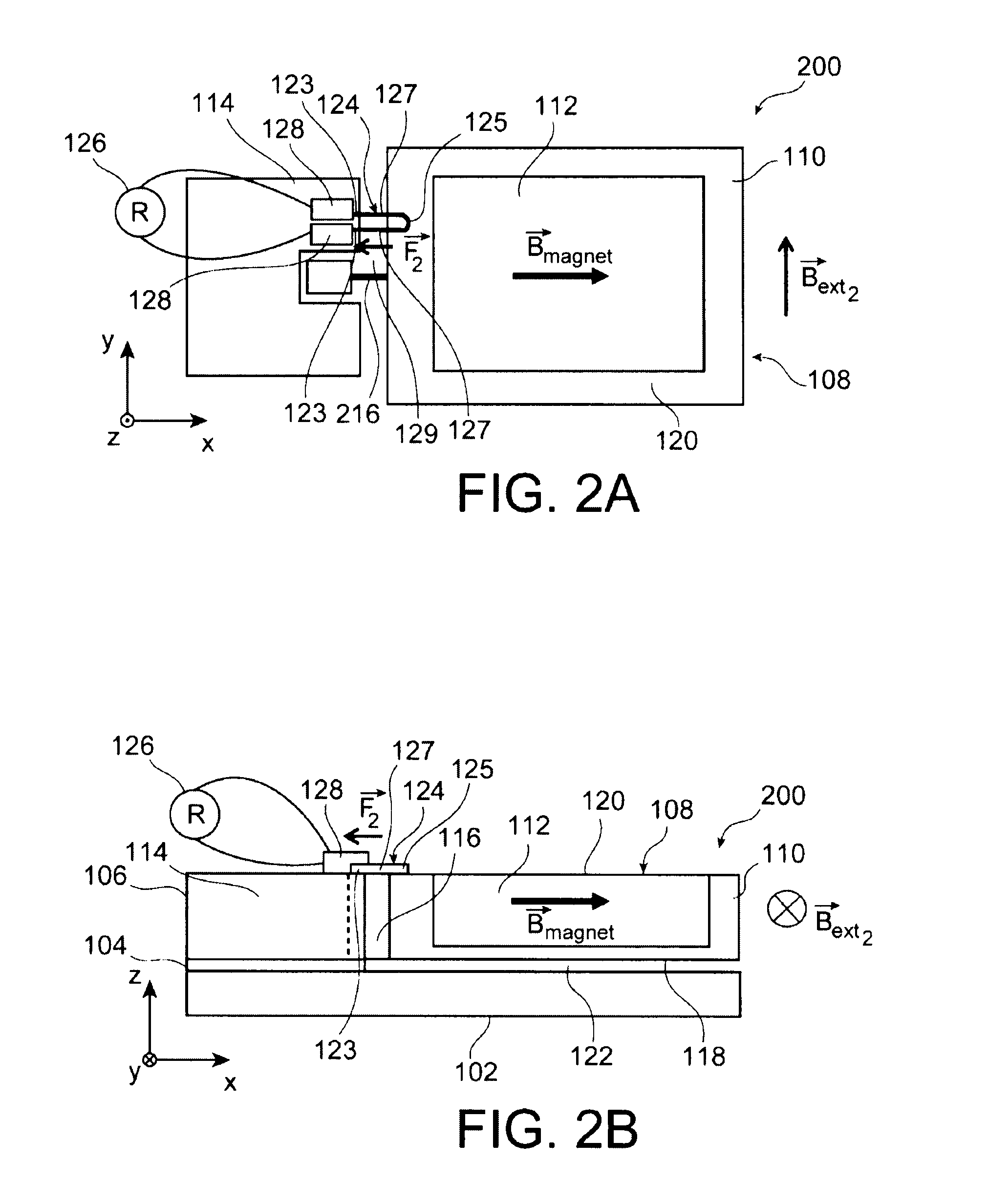
[0103]One example of a magnetic field sensor 200 will be described relative to FIGS. 2A and 2B, which respectively show a top view and a profile view of the sensor 200.

[0104]Similarly to the sensor 100 according to the first embodiment, the sensor 200 is made from a SOI substrate having layers 102, 104 and 106 (not shown in FIG. 2A), and comprises the body 108, the inlay portion 114, the stress gauge 124 and the measuring means 126.

[0105]Relative to the sensor 100, the sensor 200 is not intended to detect a magnetic field perpendicular to the plane of the sensor 200 (similar to the plane of the sensor 100 and parallel to the plane (X,Y)), but a magnetic field Bext2 oriented in the plane of the sensor 200, here parallel to the Y axis, and perpendicular to the magnetization direction Bmagnet.

[0106]To perform such a detection, the body 108 is not connected to the inlay zone 114 by the two hinges 116, but by a single hinge 216 connected to the body 108 over the entire thickness thereof...

third embodiment

[0113]One example of this magnetic field sensor 300 will be described in connection with FIGS. 5A and 5B, which respectively show a top view and a profile view of the sensor 300.

[0114]This sensor 300 has a first detection structure 100a similar to the sensor 100 previously described. Moreover, the sensor 300 also has a second detection structure 100b having the same elements as the first detection structure 100a, but arranged differently. The bodies 108a and 108b of the two detection structures 100a and 100b are similar, the ferromagnetic materials 112a and 112b of the two structures 100a, 100b having the same magnetization direction (Bmagnet) oriented parallel to the Z axis. However, the other elements of the two detection structures 100a and 100b, i.e. the inlay portions 114a, 114b, the hinges 116a, 116b, the detection means 124a, 124b and the electric contacts 128a, 128b are arranged axially symmetrically to each other relative to the others along an axis perpendicular to the pl...


PUM

PropertyMeasurementUnit
thicknessaaaaaaaaaa
thicknessaaaaaaaaaa
thicknessaaaaaaaaaa

Abstract

A magnetic field sensor including a body including a magnetic mechanism capable of forming a torque applied on the body by action of an external magnetic field to be detected; a connector, separated from the body, mechanically connecting the body to an inlay portion of the sensor by at least one pivot link having an axis perpendicular to the direction of the magnetic field to be detected; a detector detecting stress applied by the body by action of the torque, separated from the connector and including at least one suspended stress gauge including a first part mechanically connected to the inlay portion, a second part mechanically connected to the body, and a third part provided between the first and second parts and suspended between the inlay portion and the body.

Description

TECHNICAL FIELD[0001]The invention relates to the field of magnetic sensors, and more particularly devices and methods for measuring mono- or multi-axis magnetic fields, using a MEMS or NEMS miniature sensor.[0002]The targeted applications are for example measuring the geomagnetic fields to reconstitute an orientation (compass-type application), but also all applications that use a magnetic measuring field (remote current measurement, for example).BACKGROUND OF THE INVENTION[0003]Many technologies, based on different physics principles, have been developed to perform a magnetic field measurement using a miniature sensor. Examples in particular include Hall effect sensors, GMR (giant magnetoresistance) sensors, AMR (anisotropic magnetoresistance) sensors, fluxgate or magnetometric sensors, Lorentz force sensors, or magnetic material sensors.[0004]One of the problems frequently encountered concerns the production of a sensor able to perform a magnetic field measurement along several a...

Claims


Application Information

Patent Timeline
Patent Type & Authority Patents(United States)
IPC IPC(8): G01R33/02G01R33/022G01R33/028G01R33/038
CPCG01R33/022G01R33/0286G01R33/0283G01R33/038Y10S977/707Y10T29/4902
Inventor WALTHER, ARNAUDROBERT, PHILIPPEREDON, OLIVIER
Owner COMMISSARIAT A LENERGIE ATOMIQUE ET AUX ENERGIES ALTERNATIVES
Why Eureka
Try Eureka