Camera for mounting on a vehicle

a technology for mounting cameras and vehicles, applied in closed circuit television systems, color television details, television systems, etc., can solve the problems of affecting the quality of the finished product, the mounting position of the camera can be significantly out of the intended position, and the relative severe space restrictions of the camera, so as to eliminate potential circuit failure sources and reduce costs

Active Publication Date: 2014-10-21
MAGNA ELECTRONICS
View PDF107 Cites 66 Cited by
  • Summary
  • Abstract
  • Description
  • Claims
  • Application Information

AI Technical Summary

Benefits of technology

[0004]In a first aspect, the invention is directed to a camera for mounting on a vehicle, wherein the camera includes a front housing member that holds a lens member, an imaging element and a circuit board with at least one front electrical connector thereon, and a rear housing member that holds at least one rear electrical connector that is directly mounted to the at least one front electrical connector. By directly mounting the front and rear electrical connectors, a jumper wire is not needed, thereby reducing cost and eliminating potential sources of circuit failures that are associated with the use of jumper wires.

Problems solved by technology

In particular for certain applications, such as for some applications wherein the camera is rearwardly facing and is mounted in a rear panel on a vehicle, there can be relatively severe space restrictions for the camera.
Additionally, some cameras are relatively complex assemblies that are expensive, and that can suffer from reliability problems due to the number of components and the number of individual electrical connections that are associated therewith.
Another problem with some cameras is that their mounting position can be significantly out from their intended position due to a stack up of tolerances that may exist with the components that make up the camera and that are involved in its mounting to the vehicle panel.

Method used


Image

  • Camera for mounting on a vehicle
  • Camera for mounting on a vehicle
  • Camera for mounting on a vehicle

Examples


Embodiment Construction

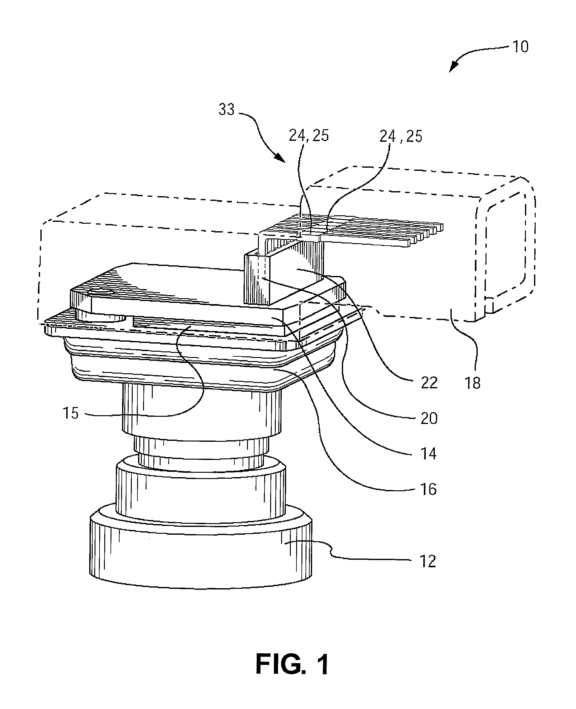
[0050]Reference is made to FIG. 1, which shows a camera 10 for use in a vehicle, and in particular for use as a rearview camera in a vehicle. The camera 10 includes a lens member 12, a circuit board 14, an imaging element 15, a front housing member 16 and a rear housing member 18 (shown for illustrative purposes only in FIG. 1 as being transparent). The lens member 12 may be any suitable lens member known in the art, and is mounted to the front housing member 16.

[0051]Note that the terms ‘front’ and ‘rear’ as used in the present document refer to the front of the camera 10 (ie. the portion of the camera where the lens member is located), and the rear of the camera 10 (ie. the portion of the camera 10 opposite the front of the camera 10). When the camera 10 is used in a rearview application in a vehicle, the front of the camera 10 thus faces rearwardly relative to the vehicle and the rear of the camera 10 faces towards the front of the vehicle.

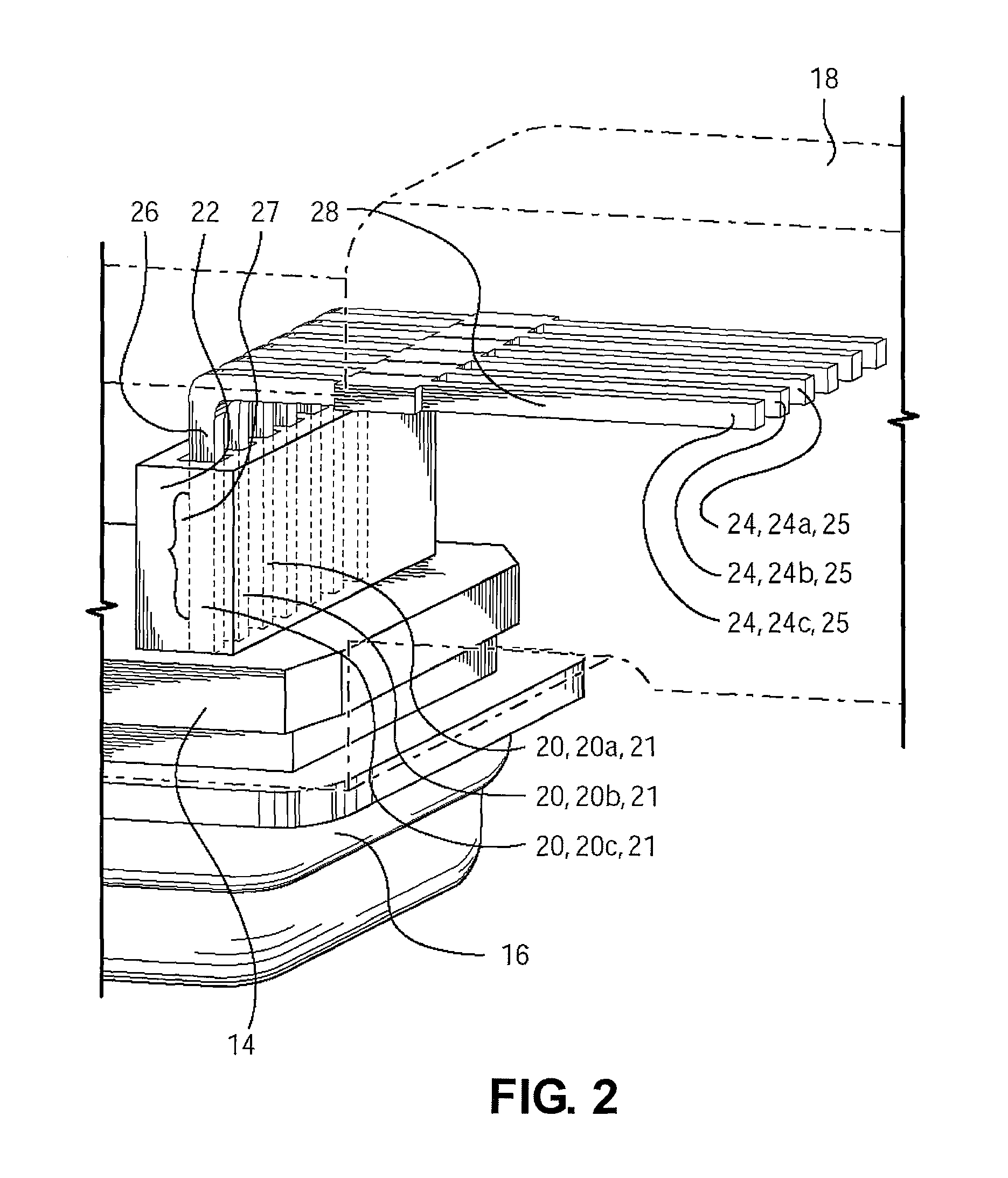
[0052]The imaging element 15 is position...


PUM


Abstract

A camera for mounting on a vehicle includes a front housing member having a first mating portion, a lens member and a circuit board having a plurality of individual front electrical connectors. The camera also includes a rear housing member having a second mating portion and a plurality of individual rear electrical connectors with first connector portions of the individual rear electrical connectors extending from the rear housing member to make electrical connection with an electrical connector of the vehicle. Second connector portions of at least some of the rear electrical connectors are configured for making electrical connection to a respective at least some of the front electrical connectors when the first and second mating portions are mated together and an alignment structure aligns second connector portion of the rear connectors with respect to the plurality of individual front electrical connectors.

Description

FIELD OF THE INVENTION[0001]The present invention relates to a camera for use in vehicles, and more particularly rearview cameras for use in vehicles.BACKGROUND OF THE INVENTION[0002]A typical camera for mounting on a vehicle has a lens member, an imaging element, a circuit board and housing members that connect together. In particular for certain applications, such as for some applications wherein the camera is rearwardly facing and is mounted in a rear panel on a vehicle, there can be relatively severe space restrictions for the camera. Additionally, some cameras are relatively complex assemblies that are expensive, and that can suffer from reliability problems due to the number of components and the number of individual electrical connections that are associated therewith. Another problem with some cameras is that their mounting position can be significantly out from their intended position due to a stack up of tolerances that may exist with the components that make up the camera...

Claims


Application Information

Patent Timeline
Patent Type & Authority Patents(United States)
IPC IPC(8): H04N5/225
CPCH04N5/2254H04N5/2252B60R11/04H04N23/51H04N23/55
Inventor MCELROY, CLARENCE PATRICKSESTI, MATTHEW C.RIEDEN, RICHARDBYRNE, STEVEN V.
Owner MAGNA ELECTRONICS
Why Eureka
Try Eureka